The function initializes the Mars Rover object in Python and maps the 5 servos to the specified pins.
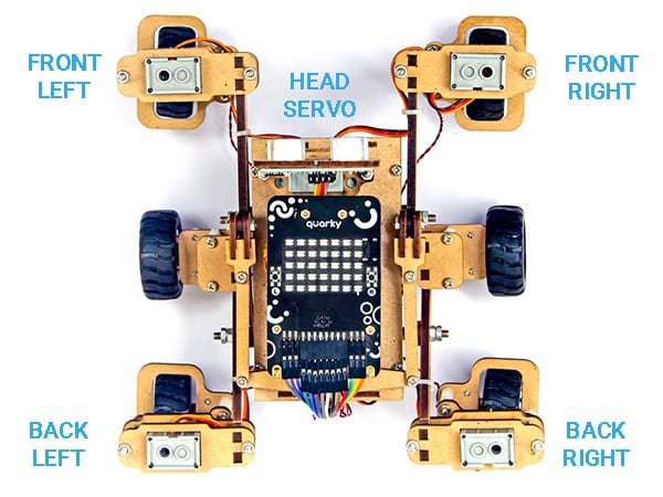
By default the following configuration is added:
- Head Servo – 4
- Front Left Servo – 1
- Front Right Servo – 5
- Back Left Servo – 2
- Back Right Servo – 6
Function Definition: MarsRover(Head = 4, Front Left = 1, Front Right = 7, Back Left = 2, Back Right = 6)
| Name | Type | Description | Expected Values | Default Value |
|---|---|---|---|---|
| Head | int | Servo Port Number at which the Head Servo Motor is connected. | 1-8 | 4 |
| Front Left | int | Servo Port Number at which the Front Left Servo Motor is connected. | 1-8 | 1 |
| Front Right | int | Servo Port Number at which the Front Right Servo Motor is connected. | 1-8 | 7 |
| Back Left | int | Servo Port Number at which the Back Left Servo Motor is connected. | 1-8 | 2 |
| Back Right | int | Servo Port Number at which the Back Right Servo Motor is connected. | 1-8 | 6 |
The function initializes the Mars Rover object in Python and maps the 5 servos to the specified pins.
By default the following configuration is added:

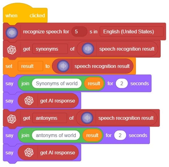
Hey! Welcome to the fascinating realm of “Synonym/Antonym World,” where the powers of Speech Recognition and ChatGPT converge. Immerse yourself in an innovative platform that not only recognizes your speech but also provides an extensive collection of synonyms and antonyms for any given word. With this powerful combination, you can effortlessly expand your vocabulary, explore alternative expressions, and delve into the nuances of language. Unleash the potential of speech recognition and ChatGPT as you navigate through a world where words find their perfect counterparts. Get ready to unlock new dimensions of linguistic exploration in the captivating Synonym/Antonym World!


In this interactive chatbox experience, the user has the freedom to specify the tone in which they would like the AI to respond. The tone can be anything they prefer: Normal, sarcastic, Friend that suits their preference.
Once the user has selected a particular tone, they can provide their input or ask a question. Based on their input, the AI will generate a response that aligns with the chosen tone. This allows for the creation of a conversational atmosphere similar to real-life interactions.
Users are encouraged to ask any question or share their thoughts on various topics. They can also engage in discussions or seek assistance with the information they need. The AI is there to facilitate a meaningful conversation and provide helpful responses based on the tone chosen by the user.
So, the user is requested to let the AI know the specific tone they would like it to adopt, and then they are free to ask any question they have in mind. The AI is here to provide a personalized and engaging chat experience!
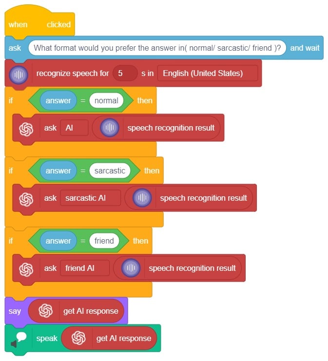
In summary, we can describe it as a chatbox that provides answers in three different ways based on the user’s mood and entertainment preferences. When a question is asked, it will respond accordingly.

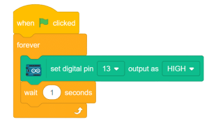
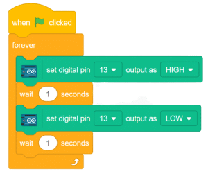
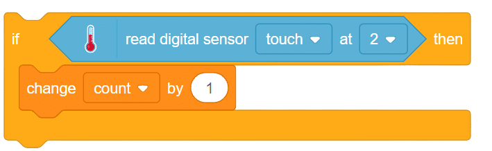
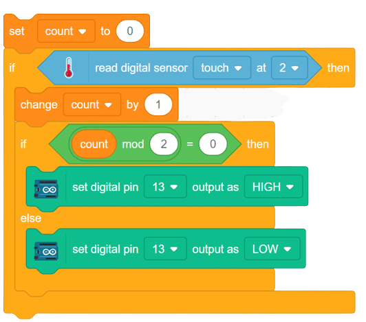
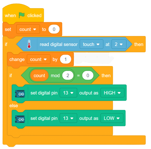
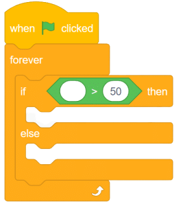
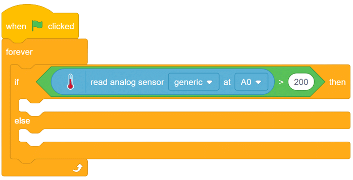
Digital pins
Arduino’s digital pins offer two voltage levels: HIGH (5V) or LOW (0V). When set to LOW, a pin provides 0V to external devices, while setting it to HIGH delivers 5V, enabling triggering of relays or LED illumination. Additionally, digital pins can function as input to read data from peripheral devices or as output to power sensors and other devices. On the other hand, analog pins are used to read analog values in the form of voltage levels ranging from 0V to 5V.
Analog pins
These are the pins that are used to read the analog values from devices in the form of voltage levels between 0v to 5v
Circuit Diagram
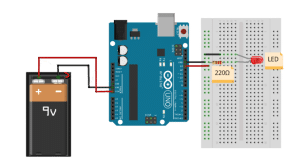
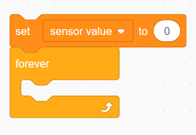
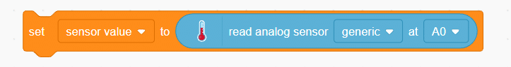
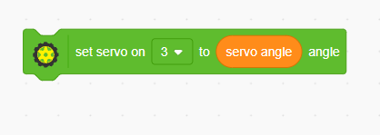
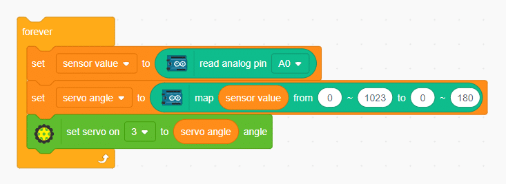
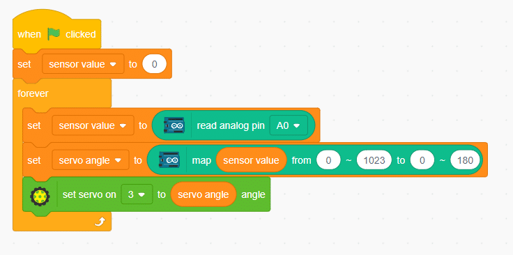
Now let’s connect our Arduino to Pictoblox and learn to code.


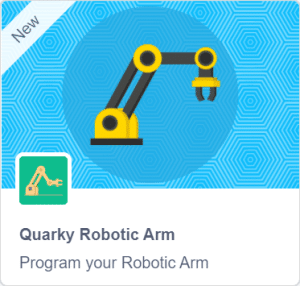
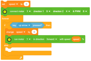
A robotic arm controlled by arrow keys allows users to manipulate its movements, specifically opening and closing the arm. This type of robotic arm is designed to respond to directional inputs from arrow keys, enabling users to control the arm’s gripping or releasing action. Users can activate the corresponding motors or actuators within the robotic arm by pressing the arrow keys, causing it to perform the desired action. This interactive control mechanism provides a user-friendly interface for operating the robotic arm, offering a hands-on experience in manipulating objects and exploring the capabilities of robotics technology.
sprite = Sprite('Tobi')

roboticArm=RoboticArm(1,2,3,4)
import time
quarky = Quarky()
while True:
  if sprite.iskeypressed("up arrow"):
    roboticArm.gripperaction("open")

  if sprite.iskeypressed("down arrow"):
    roboticArm.gripperaction("close")

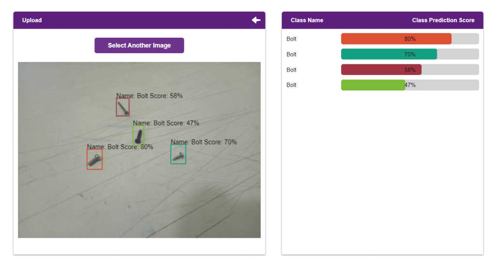
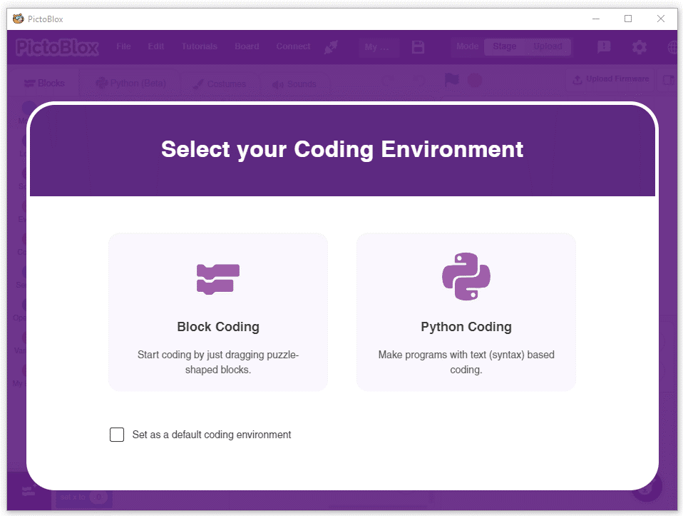
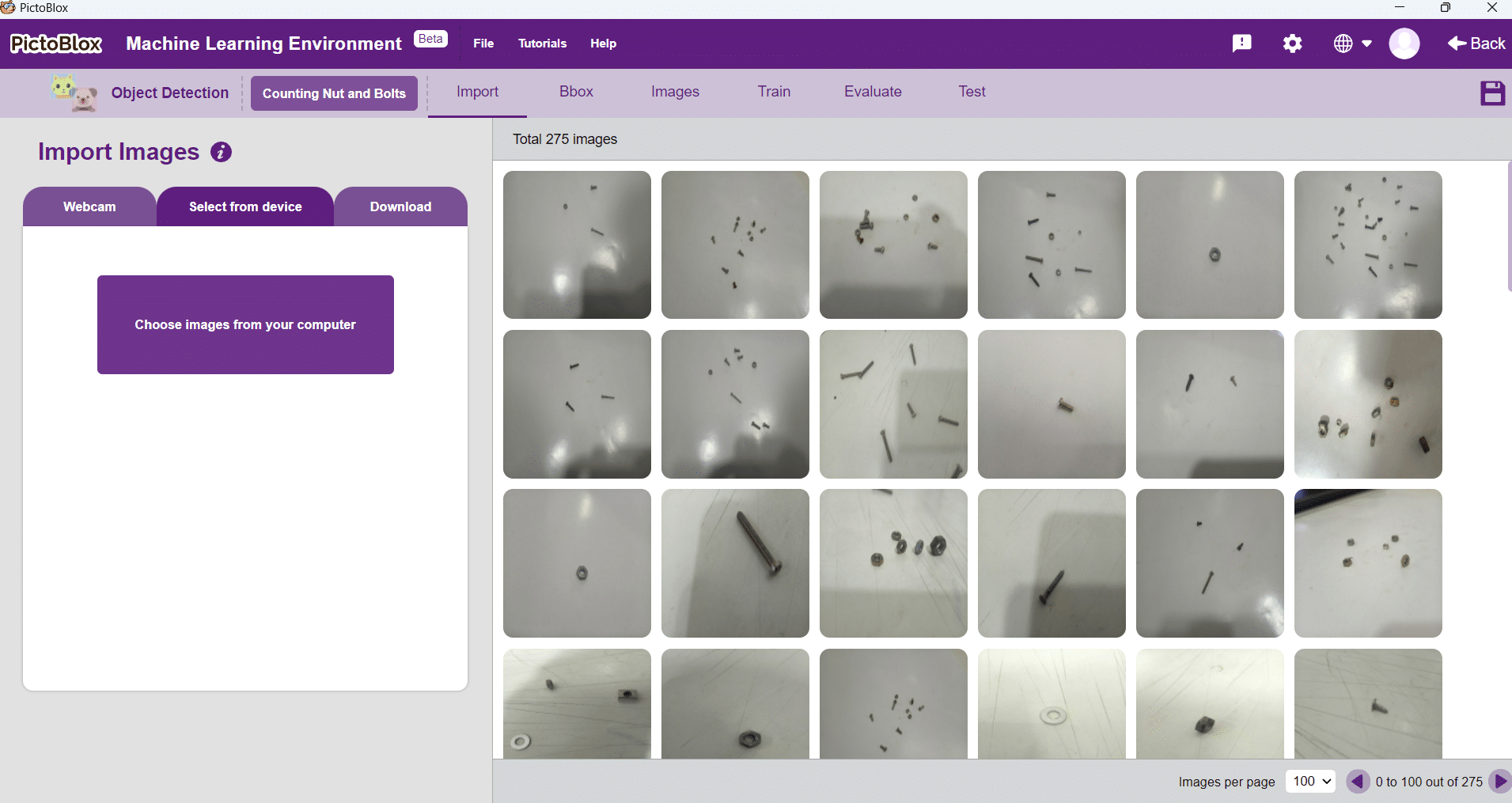
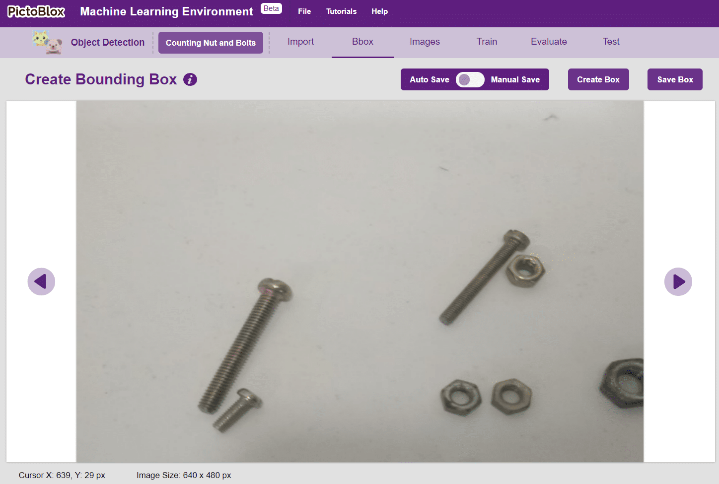
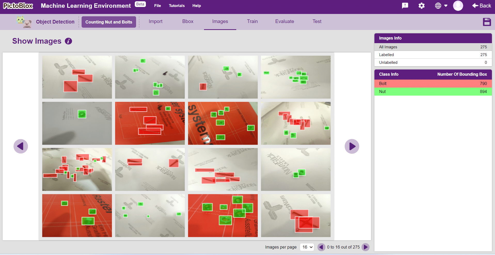
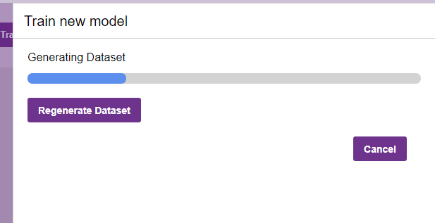
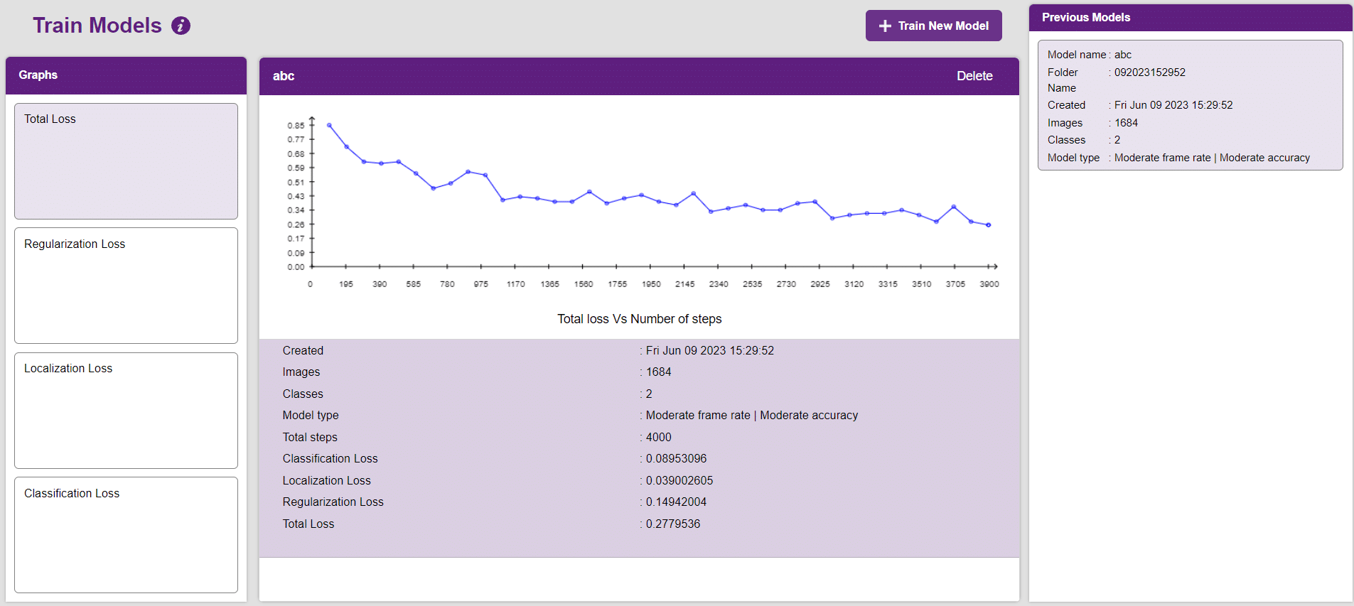
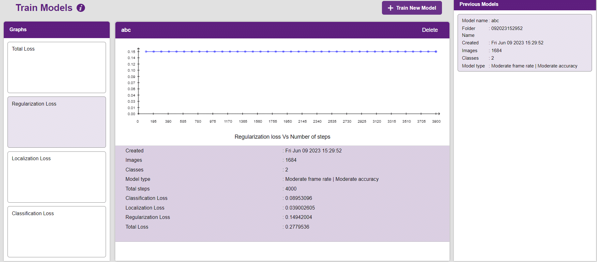
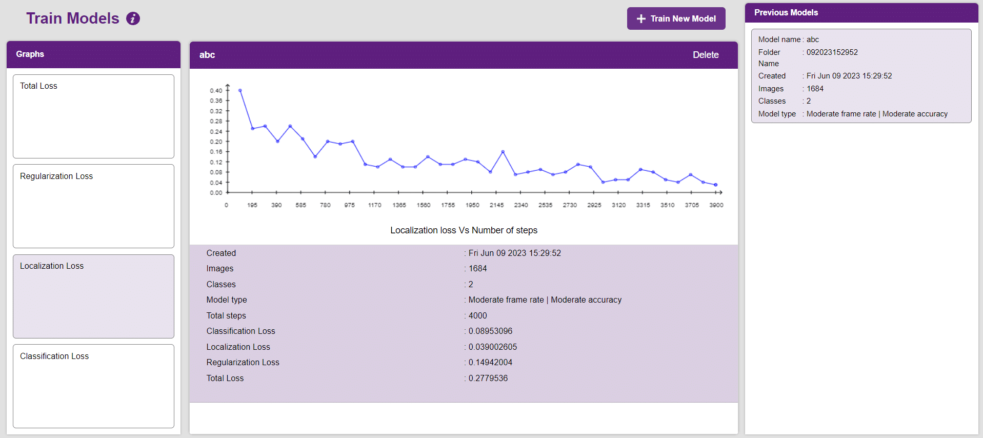
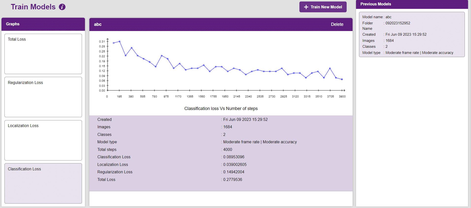
In this example project we are going to explore how to create a Machine Learning Model which can count the number of nuts and bolts from the camera feed or images. You will learn how to open the ML environment, collect and upload data, label images, train the model, and export the Python script.
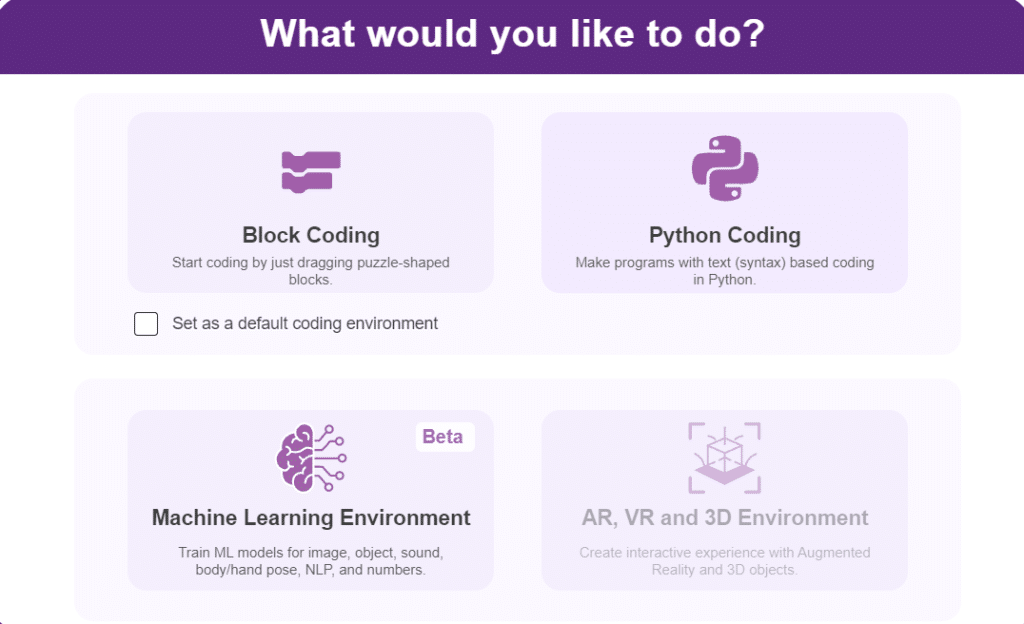
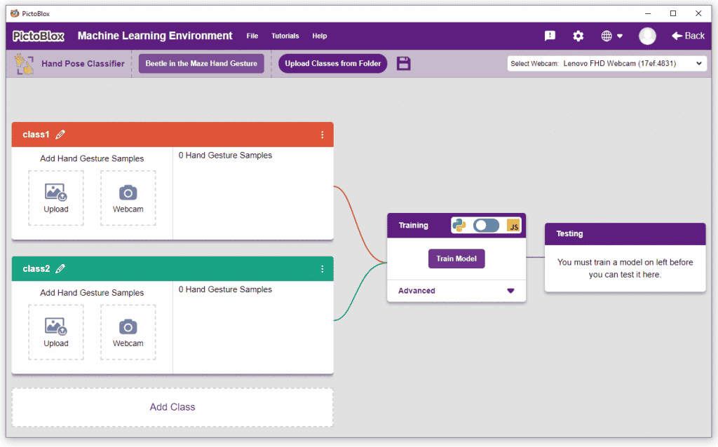
Object Detection is an extension of the ML environment that allows users to detect images and make bounding boxes into different classes. This feature is available only in the desktop version of PictoBlox for Windows, macOS, or Linux. As part of the Object Detection workflow, users can add classes, upload data, train the model, test the model, and export the model to the Block Coding Environment.

Alert: The Machine Learning Environment for model creation is available in the only desktop version of PictoBlox for Windows, macOS, or Linux. It is not available in Web, Android, and iOS versions.
Follow the steps below:
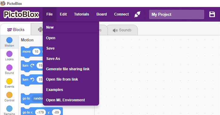
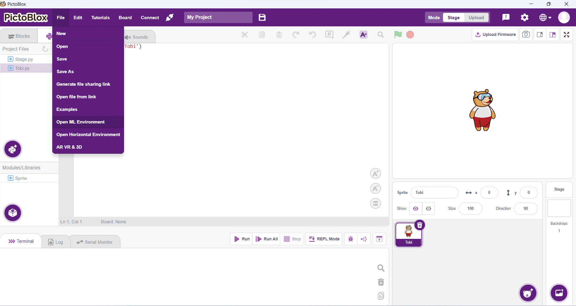
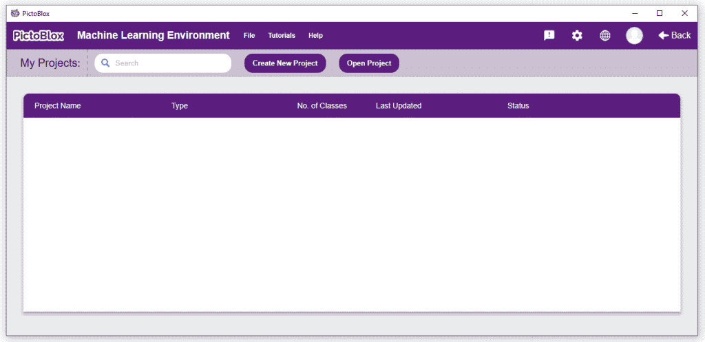
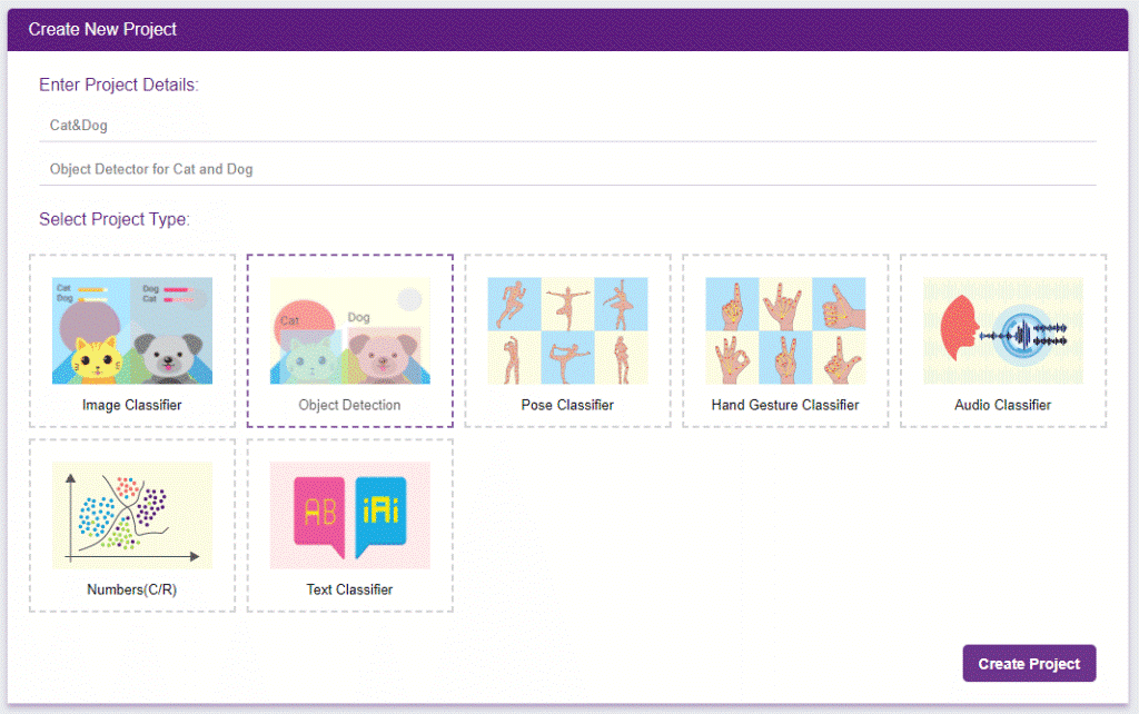
You shall see the Object Detection workflow. Your environment is all set.
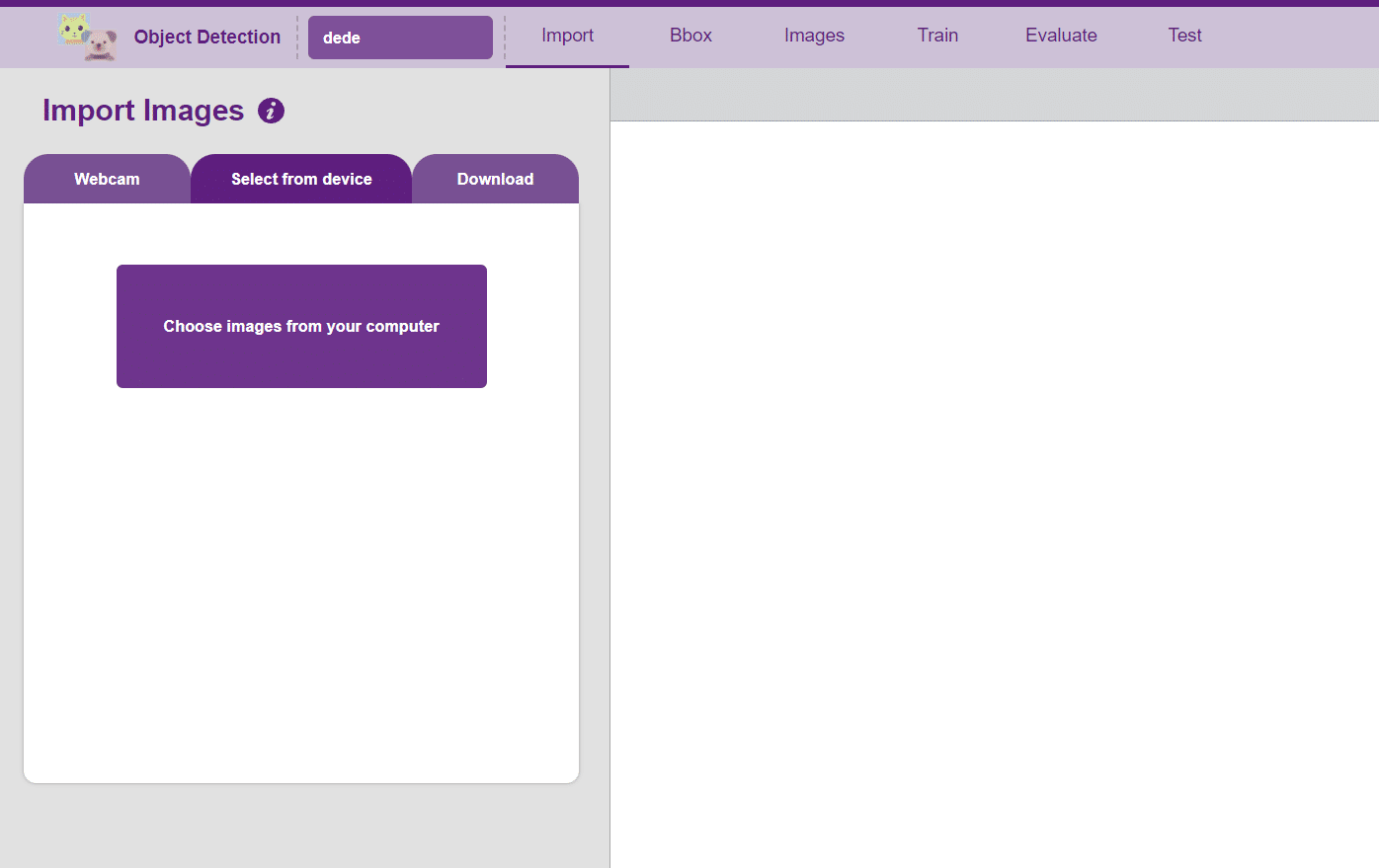
The left side panel will give you three options to gather images:
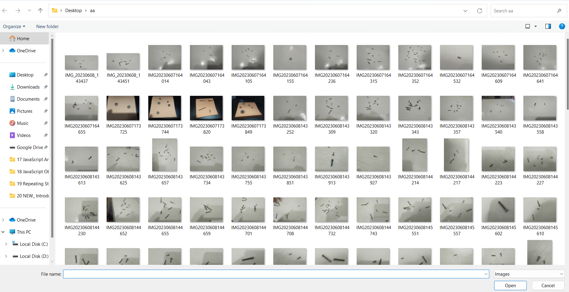
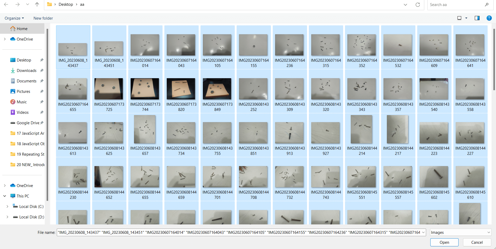
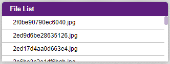
Uploading images from your device’s hard drive
A bounding box is an imaginary rectangle that serves as a point of reference for object detection and creates a collision box for that object.
We draw these rectangles over images, outlining the object of interest within each image by defining its X and Y coordinates. This makes it easier for machine learning algorithms to find what they’re looking for, determine collision paths and conserves valuable computing resources.

Notes:
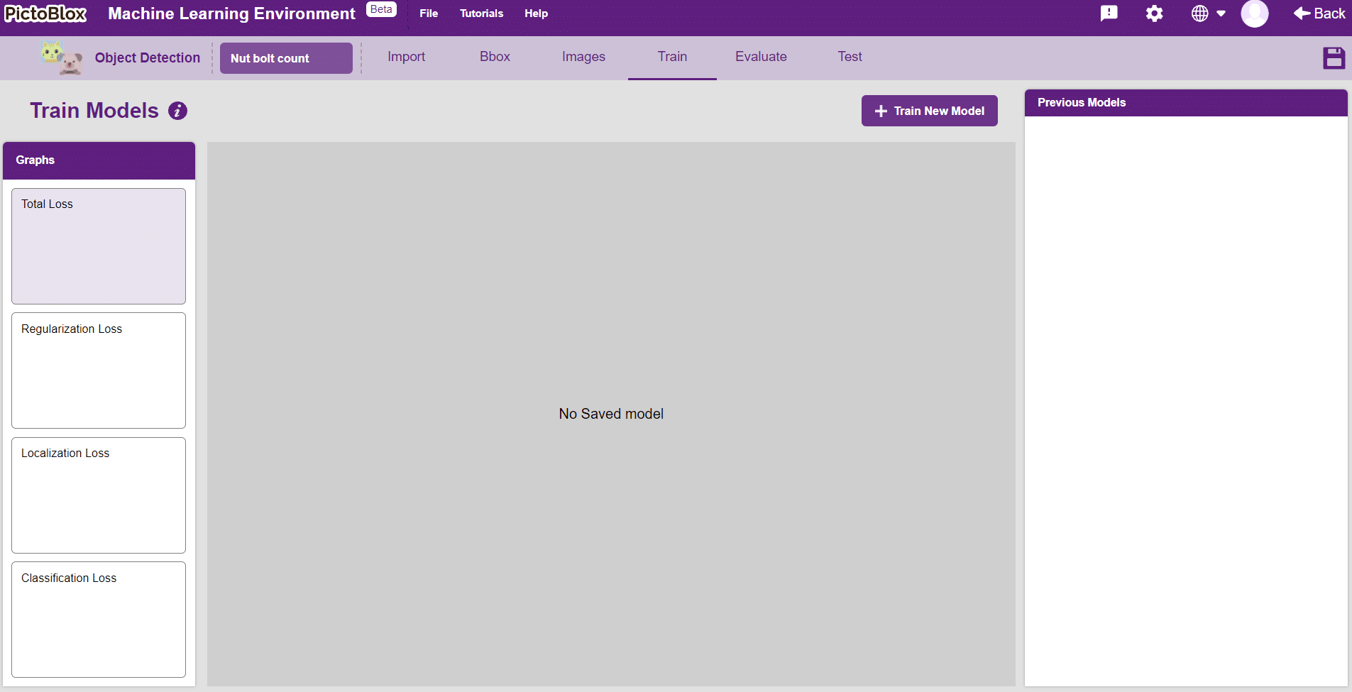
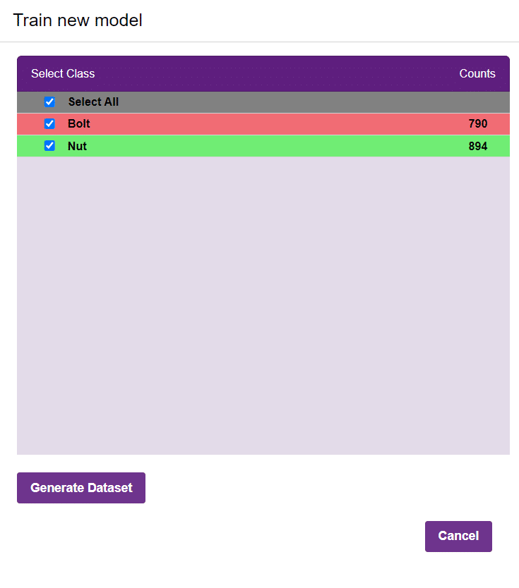
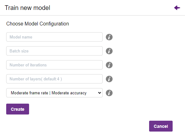
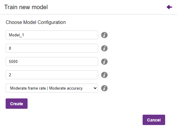
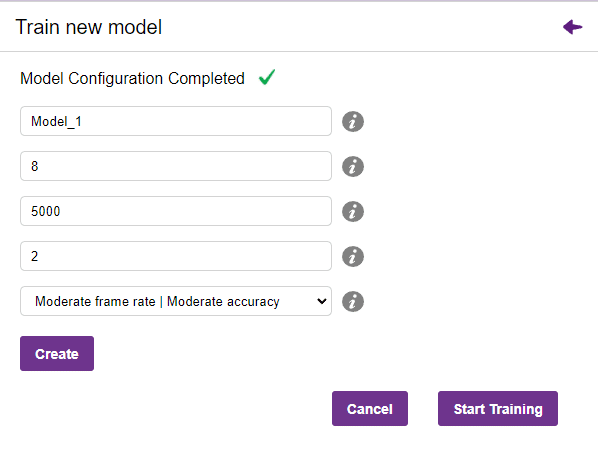
In Object Detection, the model must locate and identify all the targets in the given image. This makes Object Detection a complex task to execute. Hence, the hyperparameters work differently in the Object Detection Extension.
Now, let’s move to the “Evaluate” tab. You can view True Positives, False Negatives, and False Positives for each class here along with metrics like Precision and Recall.
The model will be tested by uploading an Image from the device:
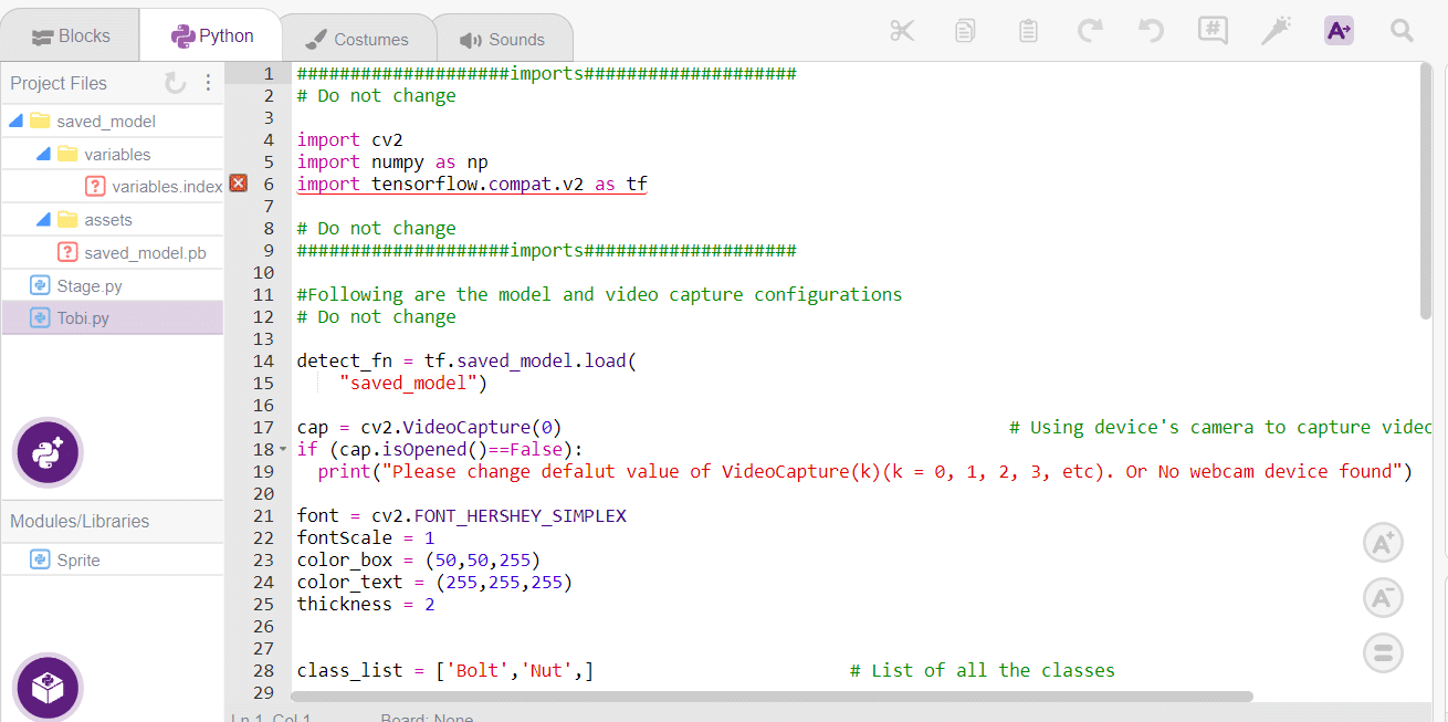
####################imports####################
# Do not change
sprite = Sprite('Tobi')
sprite1 = Sprite('Stage')
import cv2
import numpy as np
import tensorflow.compat.v2 as tf
import os
import time
# Do not change
####################imports####################
#Following are the model and video capture configurations
# Do not change
detect_fn = tf.saved_model.load(
"saved_model")
# cap = cv2.VideoCapture(0) # Using device's camera to capture video
# if (cap.isOpened()==False):
# print("Please change defalut value of VideoCapture(k)(k = 0, 1, 2, 3, etc). Or No webcam device found")
folder="img"
for filename in os.listdir(folder):
img = cv2.imread(os.path.join(folder,filename))
if img is not None:
x=filename
a=0
b=0
y=x.split('.')
font = cv2.FONT_HERSHEY_SIMPLEX
fontScale = 1
color_box = (50,50,255)
color_text = (255,255,255)
thickness = 2
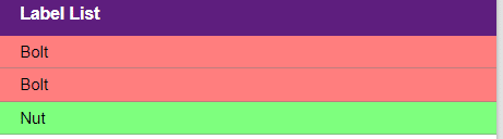
class_list = ['Bolt','Nut',] # List of all the classes
#This is the while loop block, computations happen here
image_np=img
height, width, channels = image_np.shape # Get height, wdith
image_resized = cv2.resize(image_np,(320,320)) # Resize image to model input size
image_resized = cv2.cvtColor(image_resized, cv2.COLOR_BGR2RGB) # Convert bgr image array to rgb image array
input_tensor = tf.convert_to_tensor(image_resized) # Convert image to tensor
input_tensor = input_tensor[tf.newaxis, ...] # Expanding the tensor dimensions
detections = detect_fn(input_tensor) #Pass image to model
num_detections = int(detections.pop('num_detections')) #Postprocessing
detections = {key: value[0, :num_detections].numpy() for key, value in detections.items()}
detections['num_detections'] = num_detections
detections['detection_classes'] = detections['detection_classes'].astype(np.int64)
width=320
height=320
# Draw recangle around detection object
for j in range(len(detections['detection_boxes'])):
# Set minimum threshold to 0.3
if(detections['detection_scores'][j] > 0.3):
# Starting and end point of detected object
starting_point = (int(detections['detection_boxes'][j][1]*width),int(detections['detection_boxes'][j][0]*height))
end_point = (int(detections['detection_boxes'][j][3]*width),int(detections['detection_boxes'][j][2]*height))
# Class name of detected object
className = class_list[detections['detection_classes'][j]-1]
# Starting point of text
print(className)
if(className=="Bolt"):
a=a+1
elif(className=="Nut"):
b=b+1
starting_point_text = (int(detections['detection_boxes'][j][1]*width),int(detections['detection_boxes'][j][0]*height)-5)
# Draw rectangle and put text
image_resized = cv2.rectangle(image_resized, starting_point, end_point,color_box, thickness)
image_resized = cv2.putText(image_resized,className, starting_point_text, font,fontScale, color_text, thickness, cv2.LINE_AA)
# Show image in new window
cv2.imshow("Detection Window",image_resized)
sprite1.switchbackdrop(y[0])
print(a)
print(b)
if cv2.waitKey(25) & 0xFF == ord('q'): # Press 'q' to close the classification window
break
time.sleep(2)
sprite.say("Total number of bolts is "+str(a))
time.sleep(1)
sprite.say("Total number of Nuts is "+str(b))
time.sleep(5)
sprite.say("")
cv2.waitKey(5)
cv2.destroyAllWindows() # Closes input window
The example demonstrates how to count nuts and bolts from an image of a stage. Following are the key steps happening:
Creating a Machine Learning Model to count nuts and bolts can be both complex and time-consuming. Through the steps demonstrated in this project, you can create your own Machine Learning Model that can detect and count nuts and bolts in an image. Once trained, you can export the model into the Python Coding Environment, where you can tweak it further to give you the desired output. Try creating a Machine Learning Model of your own today and explore the possibilities of Object Detection in PictoBlox!

robotic arm playing chess is a great example of how robots and AI can work together to do complex tasks. Chess is a game that needs smart thinking and careful moves. The robotic arm is like a human arm and can move pieces on the chessboard.
The robotic arm has different parts like joints, actuators, sensors, and a gripper. The joints let the arm move in different ways, just like a human arm. The actuators control the arm’s movements, so it can make precise and planned moves during the game.
The robotic arm uses AI and computer vision to play chess. The AI algorithms study the chessboard, figure out where the pieces are, and decide on the best moves. They consider things like how valuable each piece is and where they are on the board. The arm’s sensors tell it where it is, so it can pick up the pieces and put them in the right places accurately.
When the AI finds the best move, the robotic arm carefully grabs the chosen piece, lifts it up, and puts it on the right square of the chessboard. The gripper has sensors to handle the pieces gently and not damage them.
The robotic arm playing chess is an amazing example of how robots, AI, and computer vision can work together. It shows how we can use complex algorithms and physical abilities to do tasks that people usually do. This technology can be useful in many fields like manufacturing, logistics, and healthcare, where we need precise and automated movements.
In summary, a robotic arm playing chess is a cool combination of robotics, AI, and computer vision. It can make smart and accurate moves on a chessboard. It’s a big achievement in robotics and shows how automation and AI can do complex tasks in different industries.
sprite = Sprite('Tobi')


roboticArm = RoboticArm(1,2,3,4)


roboticArm.setoffset(0,-10)
roboticArm.setgripperangle(0,50)
roboticArm.sethome()
roboticArm.gripperaction("open")
roboticArm.movexyzonebyone(110,130,20,1000)
roboticArm.gripperaction("close")
roboticArm.movebyinoneaxis(40,"Z",1000)
roboticArm.movetoxyz(-100,190,30,200)
roboticArm.movexyzonebyone(-50,180,30,1000)
roboticArm.gripperaction("open")
roboticArm.movebyinoneaxis(-30,"Y",1000)
roboticArm.gripperaction("close")
roboticArm.sethome()
roboticArm.gripperaction("open")
roboticArm.movexyzonebyone(80,220,30,1000)
roboticArm.gripperaction("close")
roboticArm.movebyinoneaxis(50,"Z",1000)
roboticArm.movexyzonebyone(-70,190,30,1000)
roboticArm.gripperaction("open")
roboticArm.movebyinoneaxis(-30,"Y",1000)
roboticArm.gripperaction("close")
roboticArm.sethome()

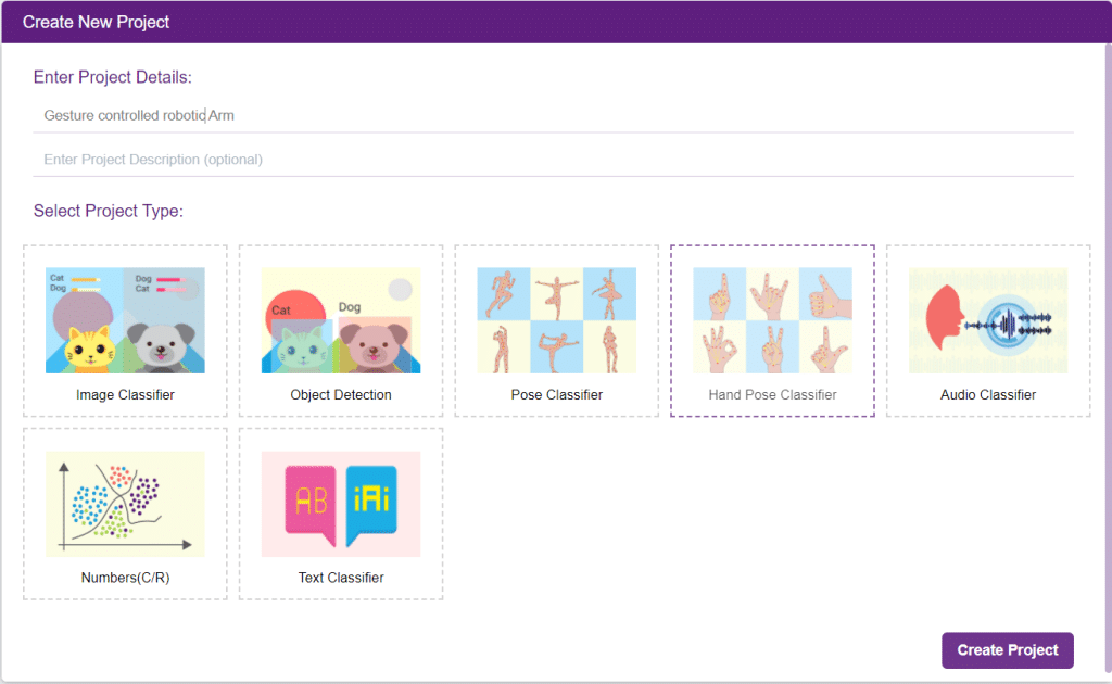
A gesture-controlled robotic arm is an innovative and interactive system that allows users to control the movements and actions of a robotic arm using hand gestures. Instead of relying on traditional input methods such as buttons or joysticks, this technology utilizes computer vision or sensor-based techniques to recognize and interpret specific hand movements or gestures.
The purpose of a gesture-controlled robotic arm is to provide a more intuitive and natural way of interacting with automatic systems. By mimicking human arm movements, users can command the robotic arm to perform various tasks, such as picking and placing objects, manipulating tools, or performing precise movements in a specific direction.
Gesture-controlled robotic arms find applications in various fields, including industrial automation, medical assistance, prosthetics, and virtual reality. They offer advantages such as enhanced dexterity, improved human-robot interaction, and increased accessibility for individuals with limited mobility.
Follow the steps below:

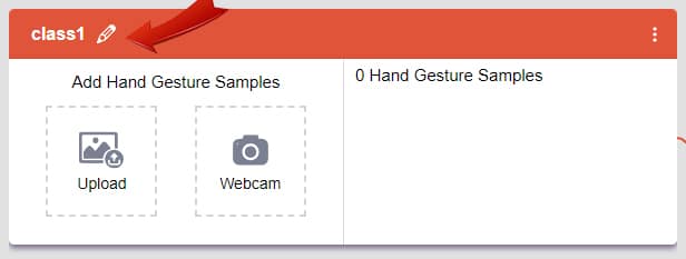
There are 2 things that you have to provide in a class:

You can perform the following operations to manipulate the data into a class.
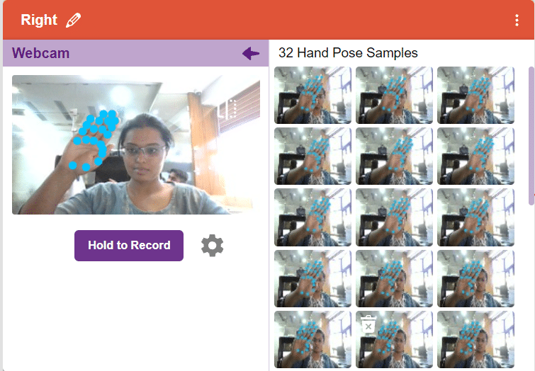
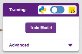
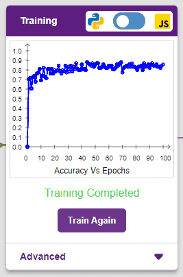
After data is added, it’s fit to be used in model training. In order to do this, we have to train the model. By training the model, we extract meaningful information from the hand pose, and that in turn updates the weights. Once these weights are saved, we can use our model to make predictions on data previously unseen.
The accuracy of the model should increase over time. The x-axis of the graph shows the epochs, and the y-axis represents the accuracy at the corresponding epoch. Remember, the higher the reading in the accuracy graph, the better the model. The range of accuracy is 0 to 1.
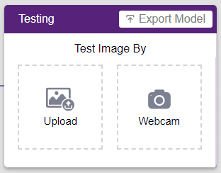
To test the model, simply enter the input values in the “Testing” panel and click on the “Predict” button.
The model will return the probability of the input belonging to the classes.
Click on the “Export Model” button on the top right of the Testing box, and PictoBlox will load your model into the Python Coding Environment if you have opened the ML Environment in Python Coding.
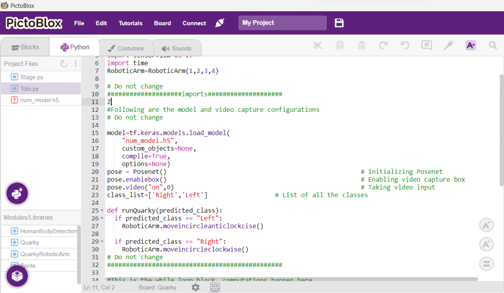
The following code appears in the Python Editor of the selected sprite.
####################imports####################
# Do not change

import numpy as np
import tensorflow as tf
import time
RoboticArm=RoboticArm(1,2,3,4)

# Do not change
####################imports####################

#Following are the model and video capture configurations
# Do not change

model=tf.keras.models.load_model(
    "num_model.h5",
    custom_objects=None,
    compile=True,
    options=None)
pose = Posenet()                                                    # Initializing Posenet
pose.enablebox()                                                    # Enabling video capture box
pose.video("on",0)                                                  # Taking video input
class_list=['Right','Left']                  # List of all the classes

def runQuarky(predicted_class):
  if predicted_class == "Left":
    RoboticArm.moveincircleanticlockcise()

  if predicted_class == "Right":
    RoboticArm.moveincircleclockwise()
      # Do not change
###############################################

#This is the while loop block, computations happen here
# Do not change

while True:
  pose.analysehand()                                             # Using Posenet to analyse hand pose
  coordinate_xy=[]

    # for loop to iterate through 21 points of recognition
  for i in range(21):
    if(pose.gethandposition(1,i,0)!="NULL"  or pose.gethandposition(2,i,0)!="NULL"):
      coordinate_xy.append(int(240+float(pose.gethandposition(1,i,0))))
      coordinate_xy.append(int(180-float(pose.gethandposition(2,i,0))))
    else:
      coordinate_xy.append(0)
      coordinate_xy.append(0)

  coordinate_xy_tensor = tf.expand_dims(coordinate_xy, 0)        # Expanding the dimension of the coordinate list
  predict=model.predict(coordinate_xy_tensor)                    # Making an initial prediction using the model
  predict_index=np.argmax(predict[0], axis=0)                    # Generating index out of the prediction
  predicted_class=class_list[predict_index]                      # Tallying the index with class list
  print(predicted_class)
  runQuarky(predicted_class)
  # Do not change
def runQuarky(predicted_class):
  if predicted_class == "Left":
    RoboticArm.moveincircleanticlockcise()

  if predicted_class == "Right":
    RoboticArm.moveincircleclockwise()

Arduino Uno is a controlling device which is capable to control the things we are connected to it, it is not a power source. motors works on the principle of electromagnetism so draws a lot of load current which can’t be maintained by Arduino, for this we need a motor driver which is integrated circuited (IC) which maintains this load current for the motors.
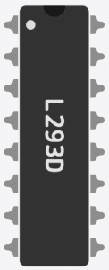
this is of 16 pin chip among which 2 are enable pins used to control the speed of the motor, 4 for the input pins are 4 for output pins for the motors, remaining are GND and VCC.
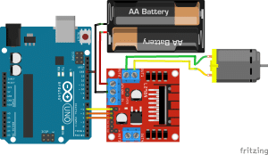
connection.
Arduino uno Motor driver
D5 IN1
D4 IN2
D6 EN1
GND GND
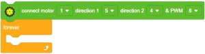
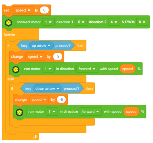
In this example, we will be controlling the direction of rotation of the motor using the motor driver.
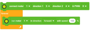
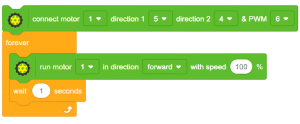

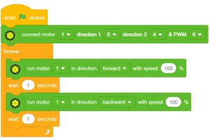

Arduino is a controlling device not a power source on the other hand, motors work on the principle of electromagnetism and hence draw a lot of load current which can’t be maintained by Arduino. To overcome this, we need a motor driver which maintains this load current along with the speed and direction control of the motor.
connections
connection.
Arduino uno Motor driver
D5 IN1
D4 IN2
D6 EN1
GND GND
![]()
If you are here willingly, it means you already possess knowledge about programming and project-making. In various programming languages, data from users is often required, and useful information needs to be displayed for users. Similarly, when writing Arduino codes and creating projects, dealing with valuable information is a common requirement. This information is termed serial data, and the process of sending or receiving data to/from the user is known as serial communication. Arduino’s Serial monitor is the interface used to display or receive data from the user.
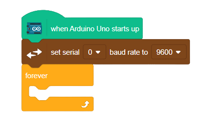
In this example, we will delve into Serial communication for Arduino using the Pictoblox communication extension.
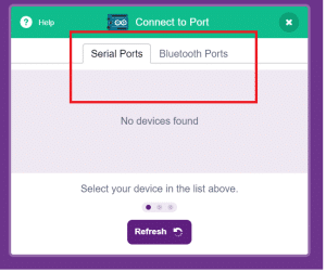
Extension Setup:
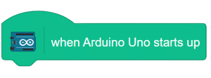
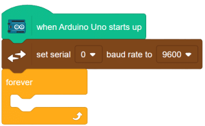
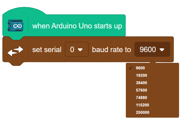
go to extension and add communication extension.
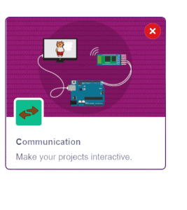
after adding the extension change the mode from stage to upload mode
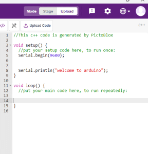
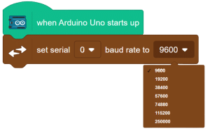
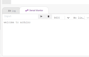
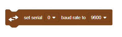
When observing the output, you may notice that it is not as expected. This issue is due to the change in the baud rate. It is crucial to set the same baud rate for the Serial monitor to ensure proper data exchange. From the highlighted space below, set the baud rate to 9600.
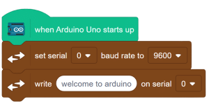
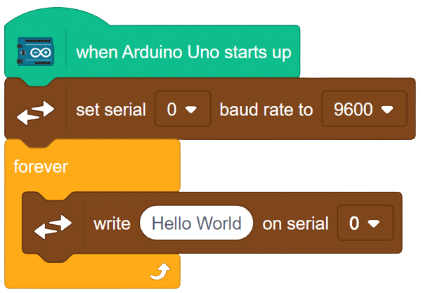
After adjusting the baud rate, observe the output again to ensure proper data display and transmission.
Here is the result after changing the baud rate.
If you encounter any unexpected output or issues with the Serial monitor, verify that the baud rate is correctly configured to avoid data discrepancies. In this comprehensive introduction, you have learned about Arduino Serial Communication with Pictoblox, including baud rate configuration and troubleshooting. Master the art of seamless data exchange between Arduino and the user, further enhancing your programming knowledge and project-making capabilities.

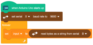
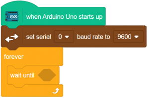
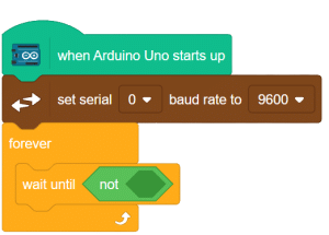
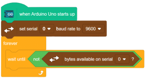
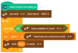
If you are here willingly, it means you already possess knowledge about programming and project-making. In programming, data from users is often needed, and valuable information needs to be displayed for users. Similarly, when coding for Arduino and creating projects, dealing with useful information is common. This information is referred to as serial data, and the process of sending or receiving data through the Serial monitor in Arduino is known as serial communication.
In this example, we will learn how to read Serial input for Arduino using the communication extension in Pictoblox.
Extension
Change the mode from “stage” to “upload.”
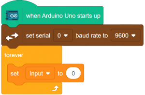

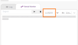
in the serial terminal, change the baud rate to 9600. enter the input in the place marked yellow. to fed this input hit the button marked in blue.
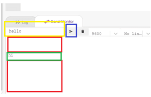
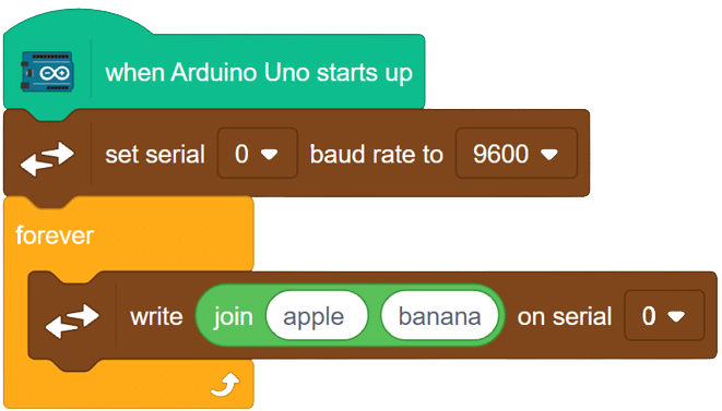
here you will notice that there are a lot of empty lines (space marked in red ) between the outputs you are entering. in the next example we will learn how to avoid such a problem.
if you are here by your own will, this means you already know about programming and project-making. in all the programming languages need some data from the user and also we are required to display some useful information for the user. in the same way, while writing the codes for Arduino and making projects, we are dealing with a lot of useful information. this data is called serial data and sending this data to the user or receiving data from the user is called serial communication. for Arduino, we are having Serial monitor from where we can show whatever the data we want to display or receive from the user.
in this example, we learn how to read the Serial input for Arduino using the communication extension of Pictoblox.
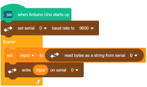
Go to extension and add communication extension.
Now change the mode from stage to upload.
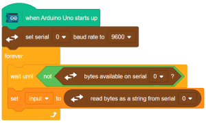
here you can see that the null spaces are gone now.


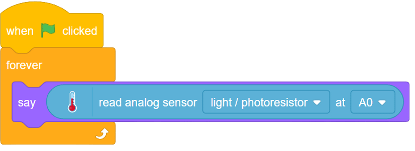
LDR, also known as a Light Dependent Resistor, is an analog-type sensor renowned for its ability to modify its resistance based on the intensity of incident light. As the surrounding light changes, the resistance of the LDR fluctuates, making it an essential component in various light-sensing applications. While generally designed as a two-pin sensor, it is also available in a three-pin module, providing enhanced features and flexibility.

in this example, we will interface our sensor module with Arduino and we’ll be reading the change in it’s resistance upon the change of light.


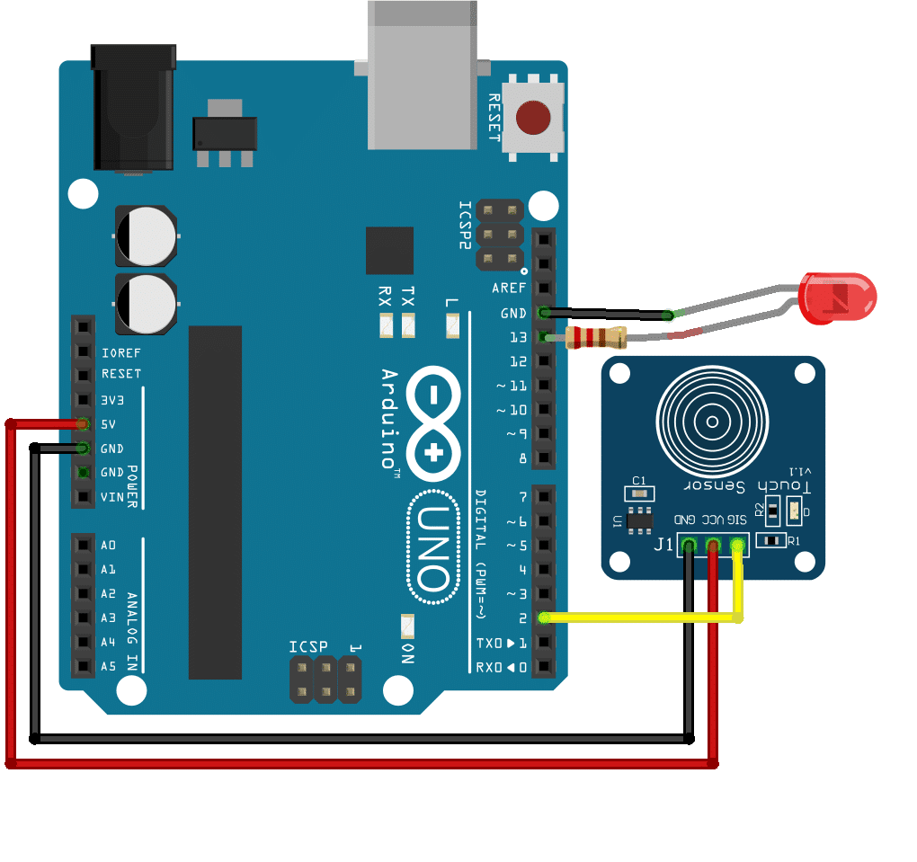
Touch sensors are innovative devices that respond to changes in capacitance resulting from static charges generated by conductive objects. Their unique working principle enables them to detect touch interactions, making them ideal for various applications, including touch-sensitive buttons and interactive surfaces.
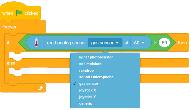
The MQ series of sensors offers a diverse range of gas detectors used for detecting multiple gases like CO2, LPG, and more. These sensors have numerous applications, from detecting smoke caused by fires in buildings to identifying gas leaks and natural gases in mining operations.
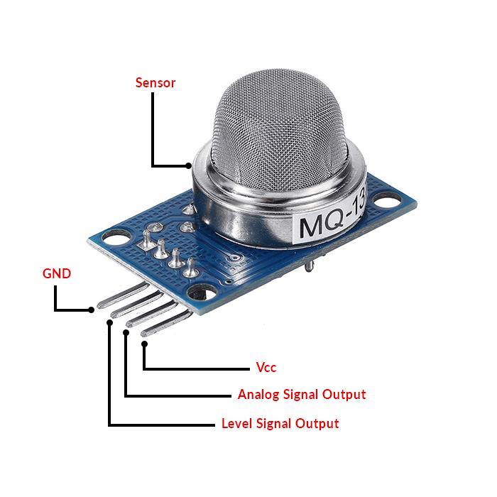
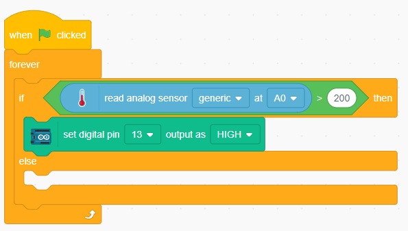
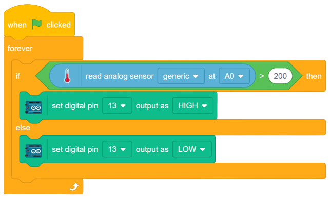
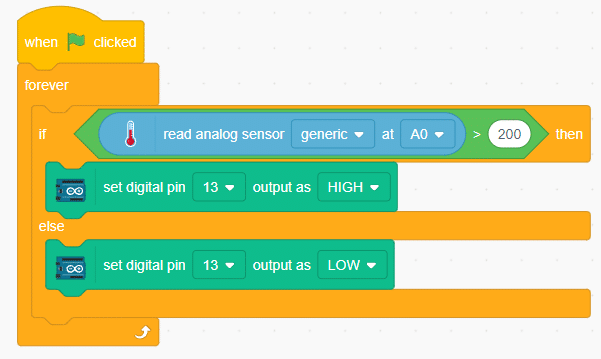
In this example, we will interface an MQ sensor with Arduino to detect gas levels above a certain threshold. When the gas levels surpass the set limit, Arduino will trigger a buzzer alarm. Let’s delve into the exciting world of gas detection using Arduino!
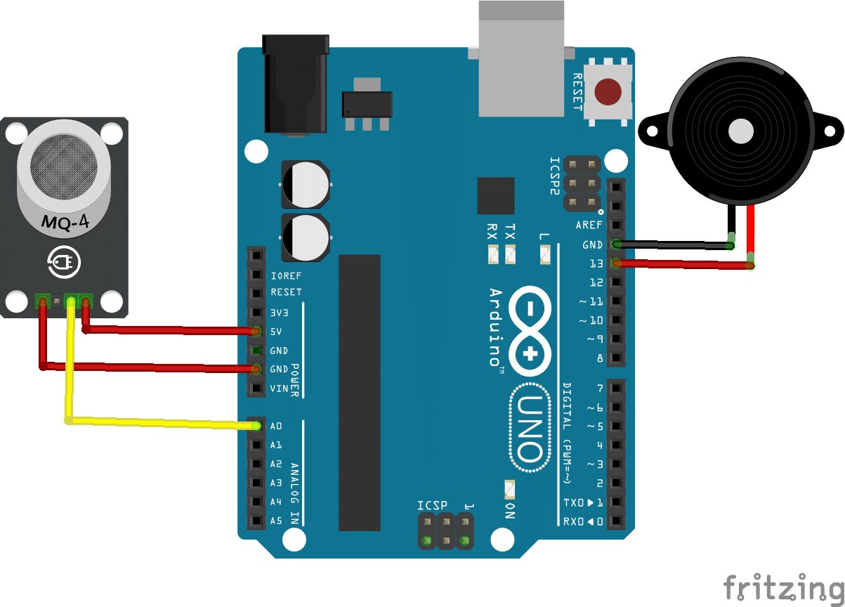
connection
Sensor Arduino
VCC 5V
GND GND
A0 A0
buzzer+ D13
Buzzer- GND
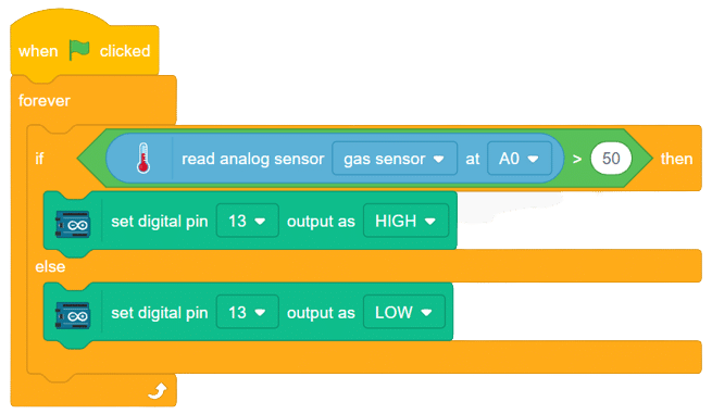


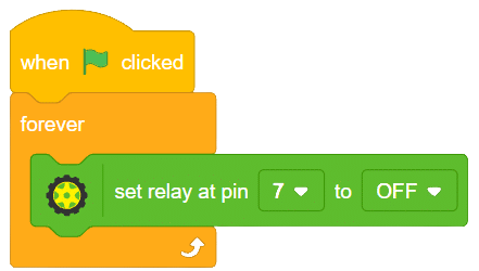
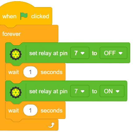
A relay is an electromagnetic switch that works on the principle of electromagnetic induction. A Realy is used to control the high voltage appliances using the microcontrollers.

a relay has a primary side which is need to be connected to the controller and the secondary side is need to be connected with the load, for example, motor, light bulb, fan, etc. primary side has 3 pins named as VCC, GND, and IN. secondary also has connections named as Common(COM), Normally Open(NO), and Normally Closed (NC).
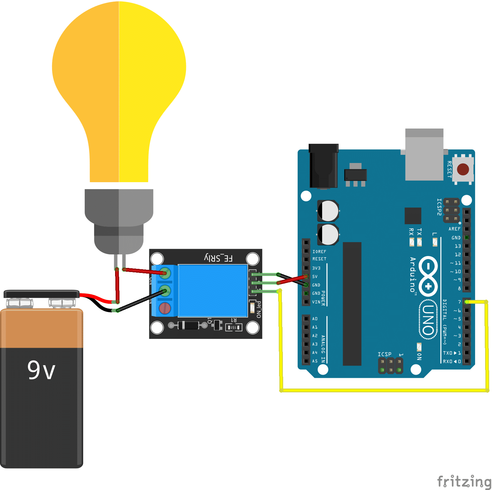
connection
relay Arduino
VCC 5V
GND GND
IN D7
COM battery-
NO 1 leg of the bulb

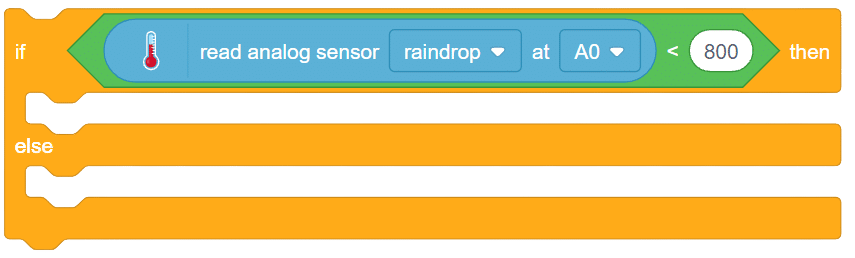
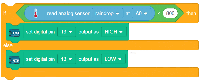
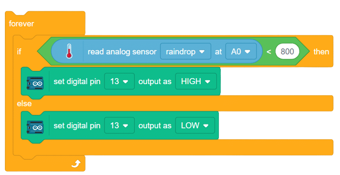
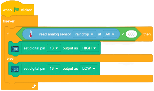
The raindrop sensor is an analog-type sensor that effectively measures changes in resistance when it encounters water. This property makes it an ideal choice for detecting rain and water presence in various applications. While typically designed with two pins, there are also versions available with a controller module, effectively converting it into a three-pin sensor for enhanced functionality.
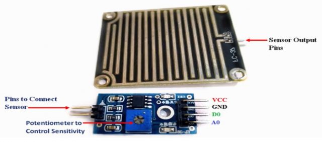
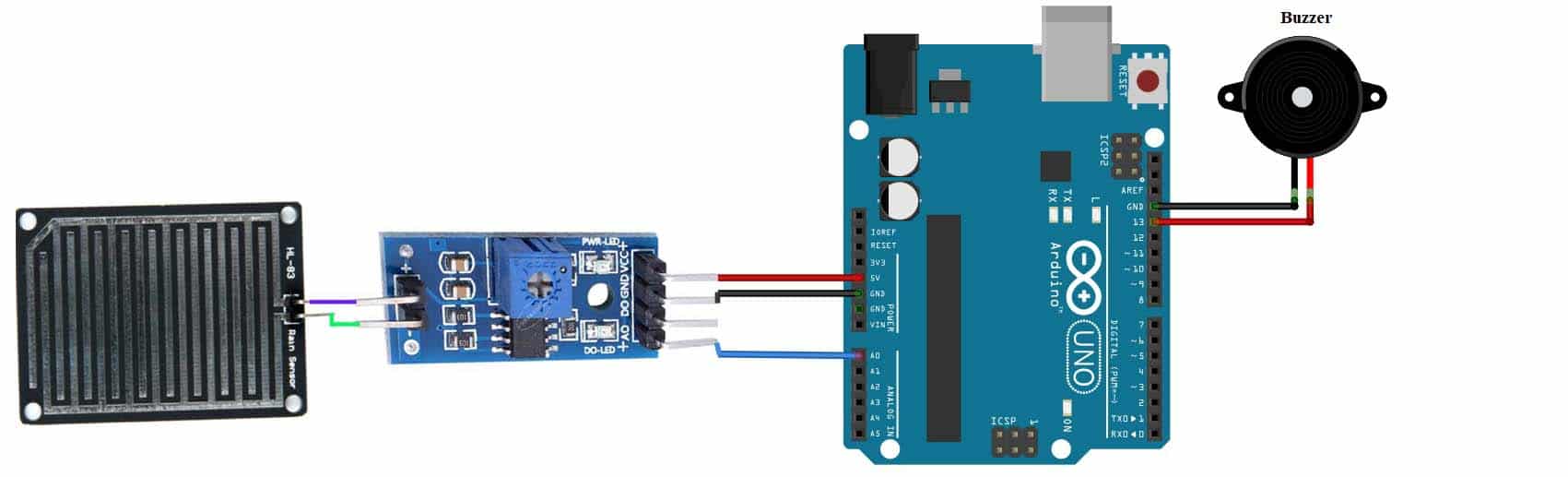
To set up the raindrop sensor circuit, make the following connections:

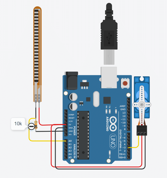
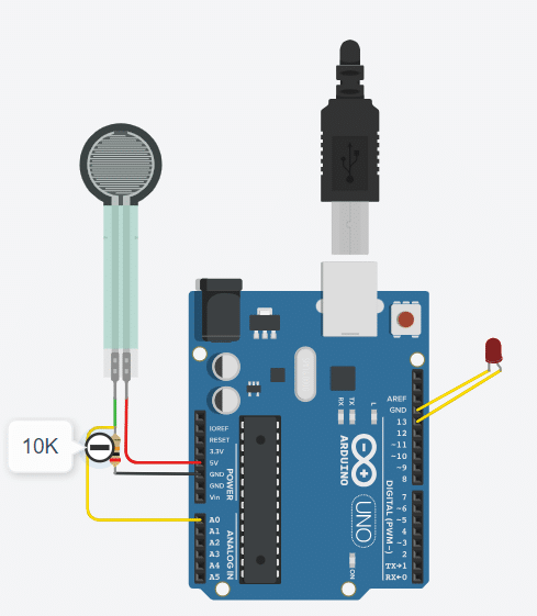
The flex sensor is an ingenious device employing carbon on a plastic strip to serve as a variable resistor. As the sensor bends in one direction, its resistance varies accordingly. The more it bends, the higher the resistance becomes. This unique property makes it an ideal choice for applications where detecting bending or flexing is necessary.
Circuit Diagram
A force sensor, also known as a load cell or force transducer, is a device designed to measure the force or load applied to it. It’s used in various applications to quantify the magnitude of forces in different directions. Force sensors are utilized in fields such as engineering, manufacturing, robotics, healthcare, and more.
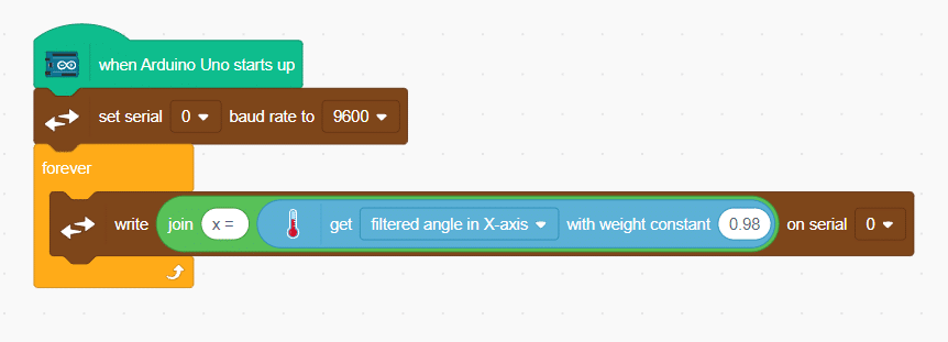
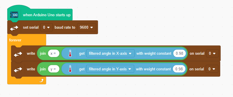
Accelerometers are vital sensors used to measure acceleration in one, two, or three axes, finding applications in robotics, gaming, and motion-sensing projects. In this example, we will guide you through connecting an MPU6050 accelerometer, a widely available 6-axis accelerometer and gyroscope module, to an Arduino board.
Our goal is to interface the accelerometer with Arduino and determine the angular movements of an object along the x-axis and y-axis.
Circuit Diagram
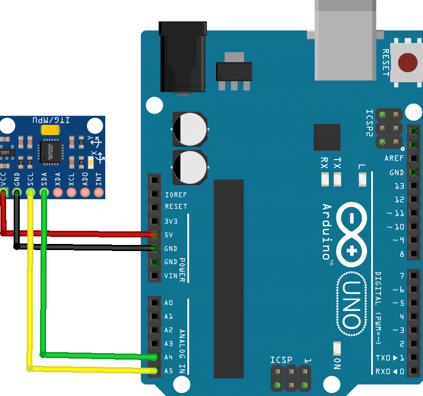
Connection
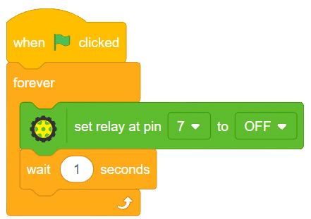
 Add a “wait” block to read the values clearly..
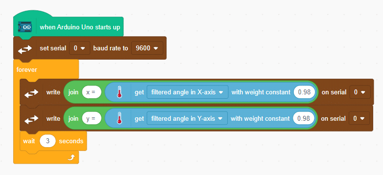


Welcome to the fascinating realm of Python Programming! In this world, we can create Python programs and save them as files with a .sb3 extension. To bring these programs to life, we’ll employ the Pictoblox interface for execution. In this particular program, we will be focusing on a simple task: printing a statement. Once our masterpiece is crafted and saved, a mere click of the [Run] button will set the script in motion, and the magic will unfold before our eyes. So, let’s dive in and embark on this exciting journey of Python programming!
print("Save Earth")
print("Preserve Future")The logic of the given Python code is quite straightforward. It consists of two separate `print` statements that each display a specific message on the screen:
1. `print(“Save Earth”)`: This line of code prints the message “Save Earth” to the console or output screen.
2. `print(“Preserve Future”)`: The second line of code prints the message “Preserve Future” to the console or output screen.
When this code is executed, the two messages will be displayed one after the other, as separate lines on the output screen, conveying the important messages: “Save Earth” and “Preserve Future.”
>> Save Earth
>> Preserve Future
Discover Python’s simplicity and versatility in this code excerpt. Learn to print messages, like “Keep Smiling,” and display user numbers. Perfect for beginners, this foundational skill opens doors to more complex coding tasks. Engage users with Python’s readability and unlock its potential to convey meaningful messages and data. Start your journey today!
message = "Keep Smiling"
print(message)
userNo = 101
print('User Number is', userNo)In summary, this Python code sets a message as “Keep Smiling” and prints it, then sets a user number as 101 and prints it along with a custom message. The output will be:
>> Keep Smiling
>> User Number is 101
Learn how to calculate the area of a rectangle with Python! Our code example shows you how to find the area by multiplying the length with the breadth. See the result for a given length of 10 and breadth of 20. Start mastering rectangle area calculations now!”
length = 10
breadth = 20
area = length * breadth
print(area)In summary, the code calculates the area of a rectangle with a length of 10 and breadth of 20 and displays the result, which would be 200.
>> 200
Discover the Python magic of finding the sum of two numbers! This code snippet showcases how to add 10 and 20 (num1 and num2) effortlessly, resulting in the sum displayed as the output. Unlock the power of Python’s simple yet essential arithmetic operation with this concise and enlightening example.
num1 = 10
num2 = 20
result = num1 + num2
print(result)In summary, the code adds the values of “num1” and “num2” (10 and 20, respectively) and displays the sum, which would be 30.
>> 30
In Python, you can convert an integer to a float using explicit type conversion. This allows you to perform mathematical operations with integers and then convert the result to a float if needed. By doing so, you can work with decimal values and have more control over the precision of your calculations.
num1 = 10
num2 = 20
num3 = num1 + num2
print(num3)
print(type(num3))
num4 = float(num1 + num2)
print(num4)
print(type(num4))The Python code provided demonstrates how to explicitly convert an integer to a float.
>> 30
>> <class ‘int’>
>> 30.0
>> <class ‘float’>
This Python code demonstrates how to convert a float to an integer using explicit type conversion. It showcases the difference in data types before and after the conversion.
num1 = 10.2
num2 = 20.6
num3 = (num1 + num2)
print(num3)
print(type(num3))
num4 = int(num1 + num2)
print(num4)
print(type(num4))>> 30.8
>> <class ‘float’>
>> 30
>> <class ‘int’>
This Python code demonstrates the process of type conversion between numbers and strings. It showcases how to add two numbers and concatenate a string to display the total price.
priceIcecream = 25
priceBrownie = 45
totalPrice = priceIcecream + priceBrownie
print("The total is Rs." + totalPrice )1. The code defines two variables, priceIcecream and priceBrownie, with their respective values.
2. It then performs addition on these variables to calculate the total price.
3. Next, it uses string concatenation to display the result as a sentence.
The output of the code will be an error due to a type mismatch. To fix this, you need to convert the totalPrice variable to a string using the str() function.
#There will be one TypeError: can only concatenate str (not “int”) to str
#Failed to execute script ‘main’ due to unhandled exception!
This Python code demonstrates the concept of explicit type casting. It calculates the total price by adding two price variables, priceIcecream and priceBrownie, and then converts the result to a string for display.
priceIcecream = 25
priceBrownie = 45
totalPrice = priceIcecream + priceBrownie
print("The total in Rs." + str(totalPrice))>> The total in Rs.70
This Python code showcases how to perform explicit type conversion and string concatenation. It uses the variables ‘icecream’ and ‘brownie’ to calculate the total price of both items.
#Explicit type conversion
icecream = '25'
brownie = '45'
#String concatenation
price = icecream + brownie
print("Total Price Rs." + price)
#Explicit type conversion - string to integer
price = int(icecream)+int(brownie)
print("Total Price Rs." + str(price))1. The code initializes two variables, ‘icecream’ and ‘brownie’, with string values representing the respective prices.
2. The code performs string concatenation using the ‘price’ variable, combining the values of ‘icecream’ and ‘brownie’.
3. The code then prints the total price in a formatted message.
4. Next, the code performs explicit type conversion by converting the values of ‘icecream’ and ‘brownie’ from strings to integers.
5. The code adds the converted values of ‘icecream’ and ‘brownie’ to calculate the total price as an integer.
6. The code converts the total price back to a string and concatenates it with the message to display the total price in a formatted message.
>> Total Price Rs.2545
>> Total Price Rs.70


Copyright 2025 – Agilo Research Pvt. Ltd. All rights reserved – Terms & Condition | Privacy Policy