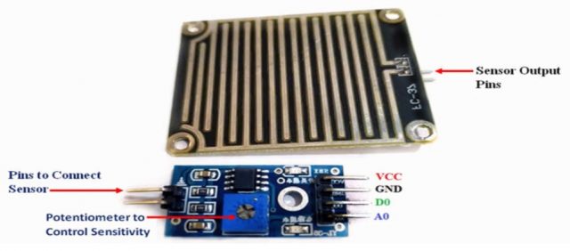
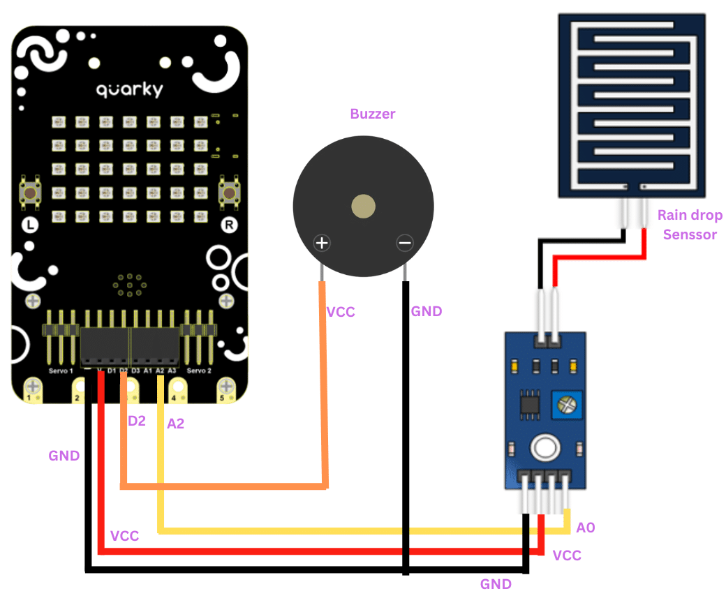
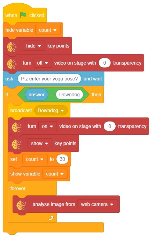
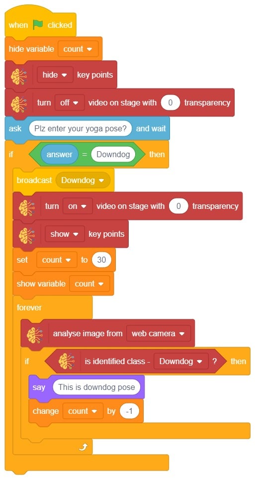
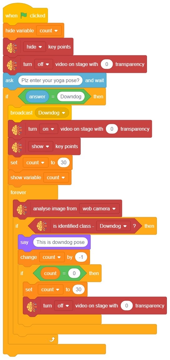
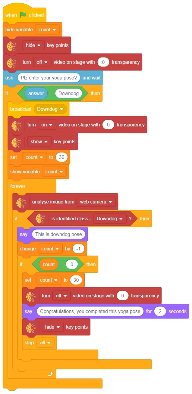
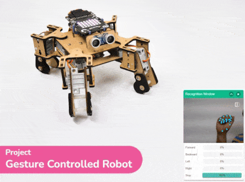
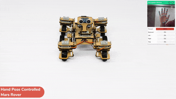
In this activity, we will try to create a new Machine Learning model that will be able to identify and detect different types of hand poses and that can help us to control the Mecanum Gripper Robot. This activity can be quite fun and by knowing the process, you can develop your own customized hand pose classifier model easily!
We will use the same model that we have created in the previous Hand Pose Controlled Mecanum model to avoid any misdirection and confusion.
Note: You can always create your own model and use it to perform any type of functions as per your choice. This example proves the same point and helps you understand well the concept of Machine Learning models and environment.
Hand Gesture Classifier Workflow
Follow the steps below:
- Open PictoBlox and create a new file.
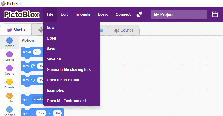
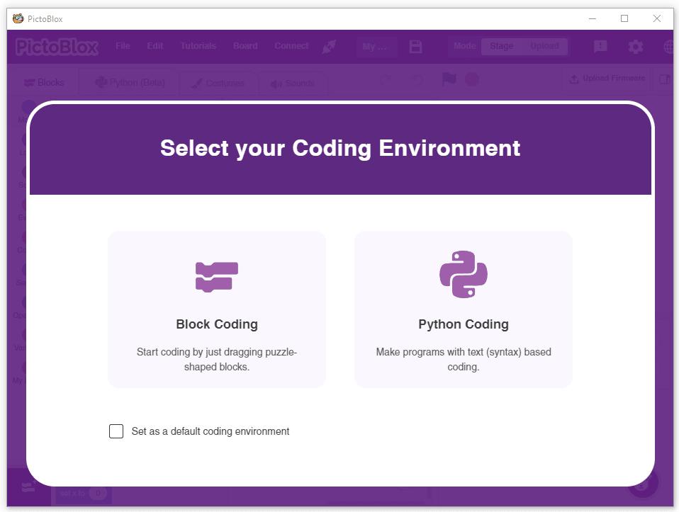
- Select the Python coding environment as appropriate Coding Environment.
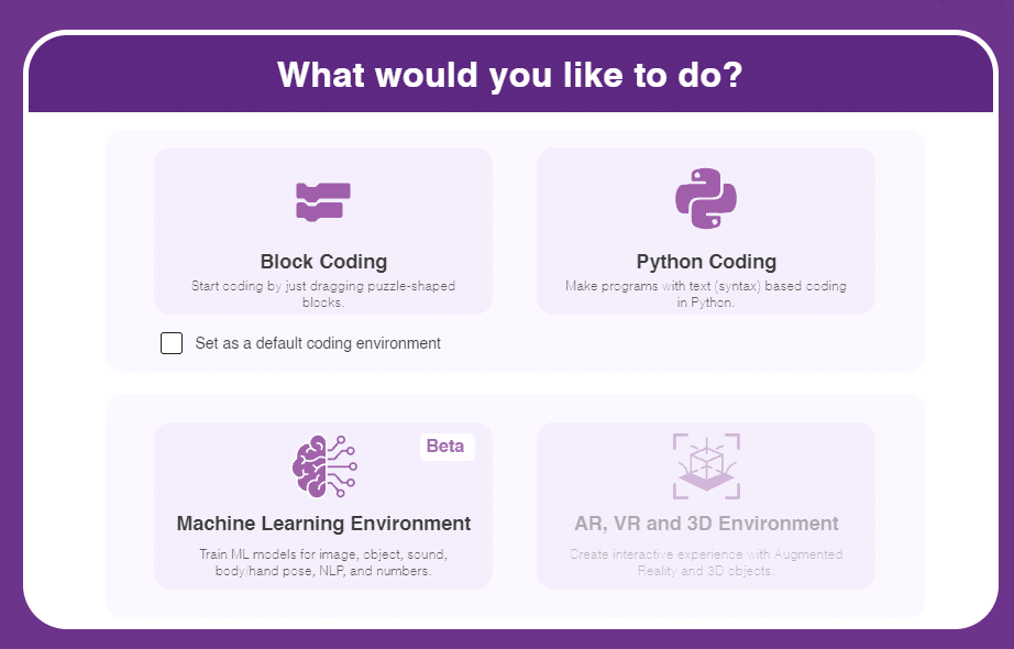
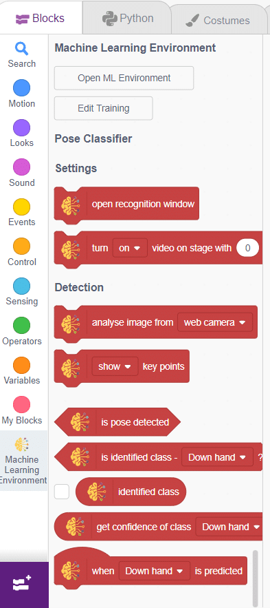
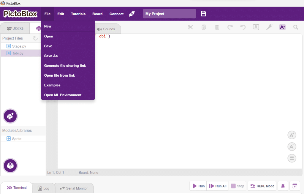
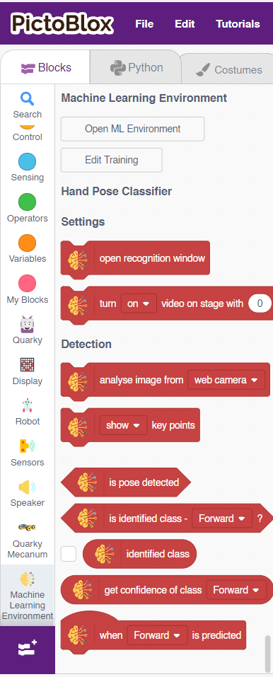
- Select the “Open ML Environment” option under the “Files” tab to access the ML Environment.
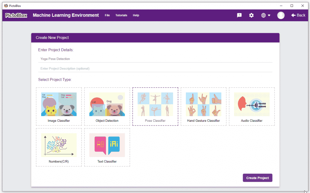
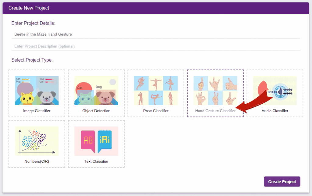
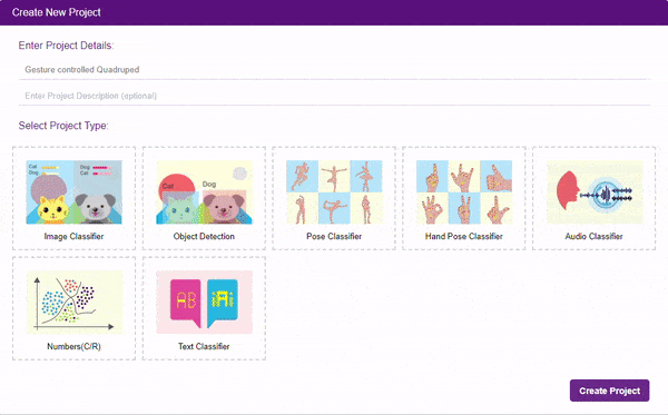
- Click on “Create New Project“.
- A window will open. Type in a project name of your choice and select the “Hand Gesture Classifier” extension. Click the “Create Project” button to open the Hand Pose Classifier window.
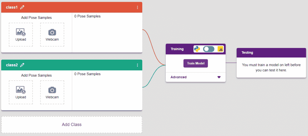
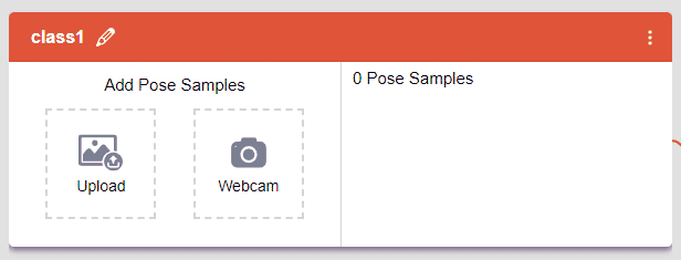
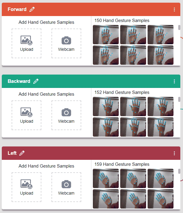
- You shall see the Classifier workflow with two classes already made for you. Your environment is all set. Now it’s time to upload the data.
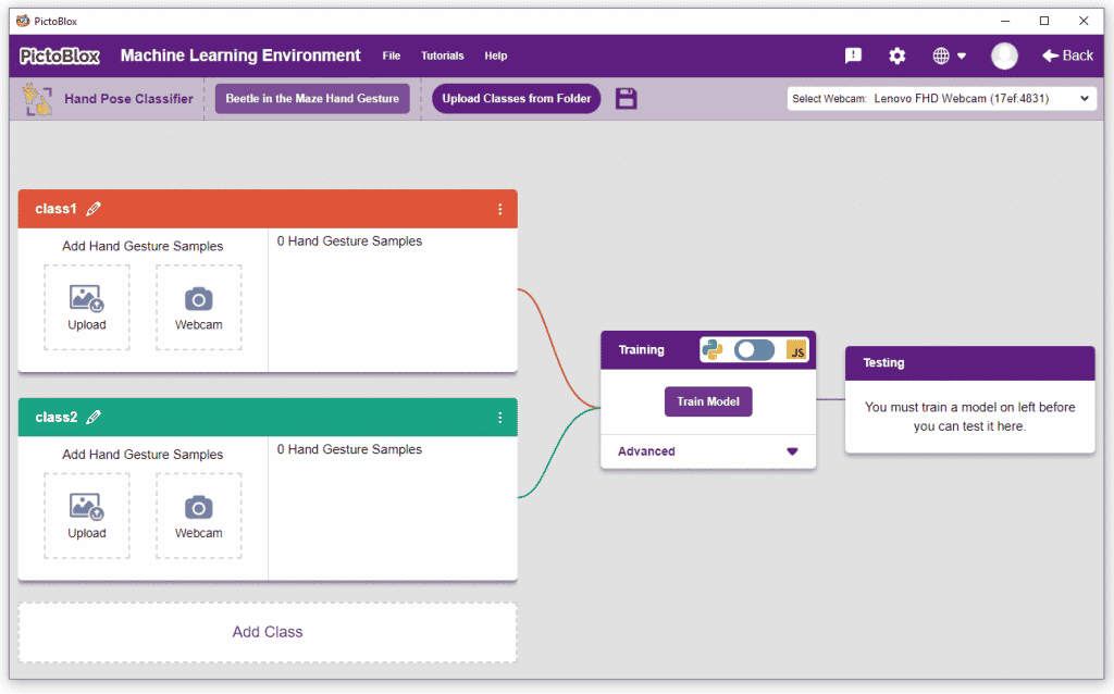
Class in Hand Gesture Classifier
There are 2 things that you have to provide in a class:
- Class Name: It’s the name to which the class will be referred as.
- Hand Pose Data: This data can either be taken from the webcam or by uploading from local storage.

Note: You can add more classes to the projects using the Add Class button.
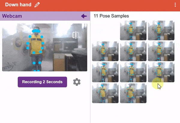
Adding Data to Class
You can perform the following operations to manipulate the data into a class.
- Naming the Class: You can rename the class by clicking on the edit button.
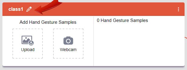
- Adding Data to the Class: You can add the data using the Webcam or by Uploading the files from the local folder.
- Webcam:
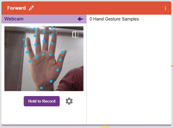
Note: You must add at least 20 samples to each of your classes for your model to train. More samples will lead to better results.
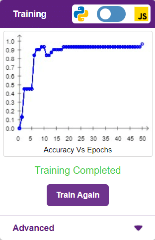
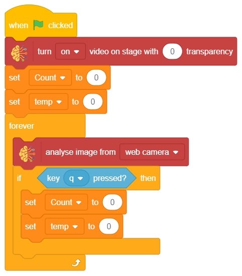
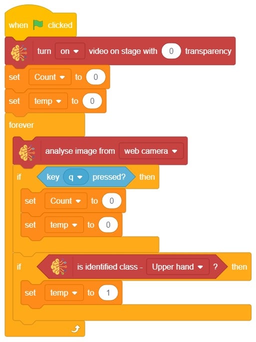
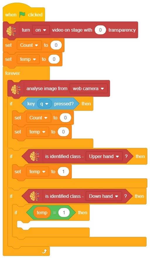
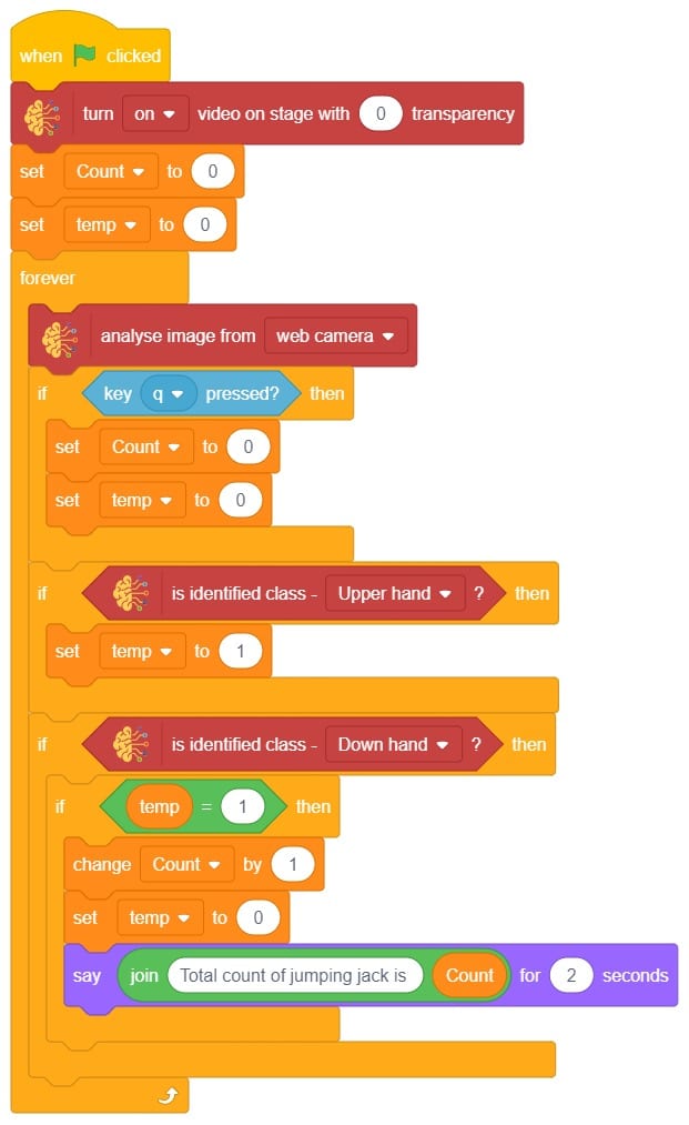
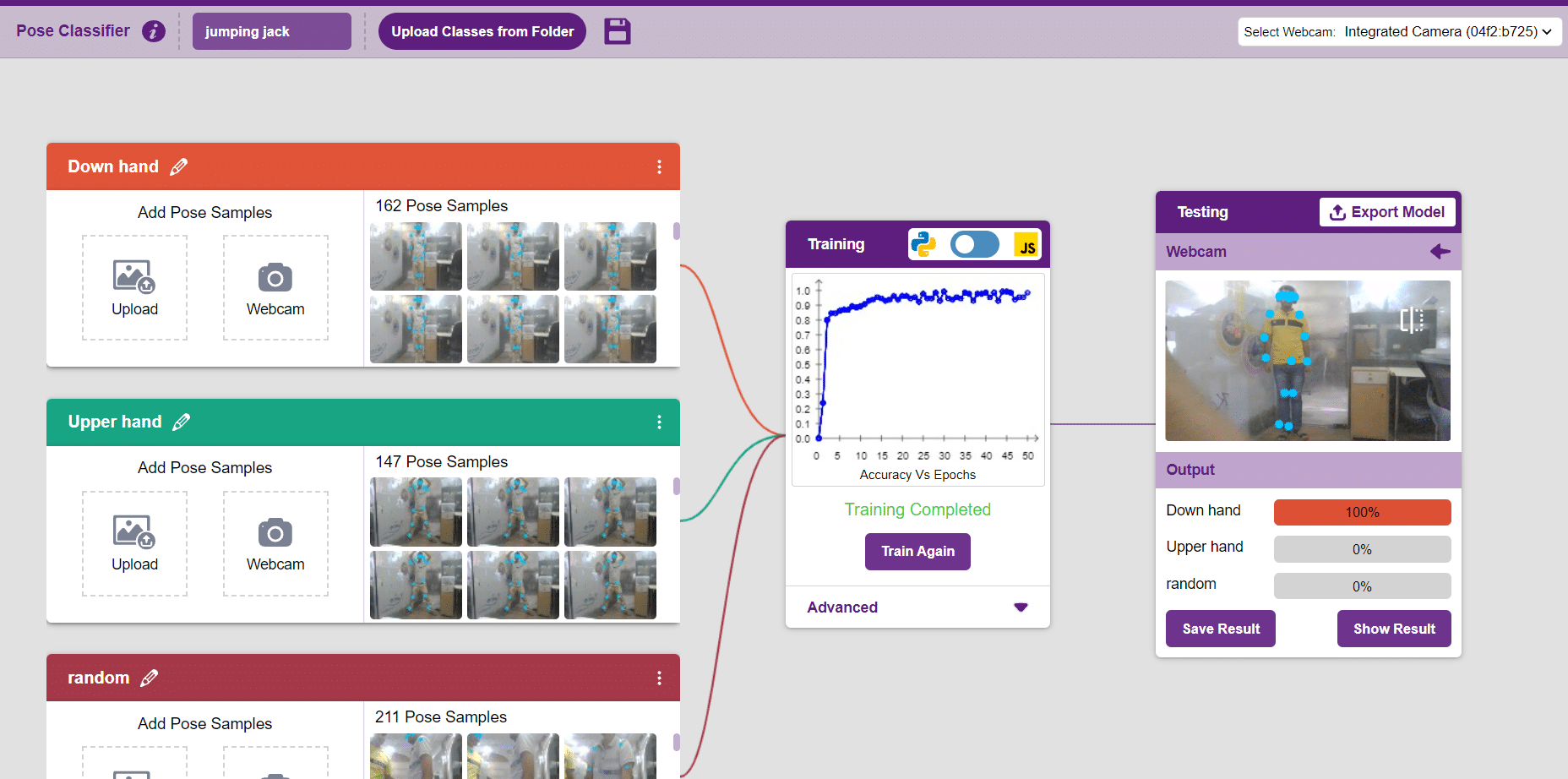
Training the Model
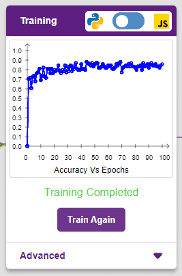
After data is added, it’s fit to be used in model training. In order to do this, we have to train the model. By training the model, we extract meaningful information from the hand pose, and that in turn updates the weights. Once these weights are saved, we can use our model to make predictions on data previously unseen.
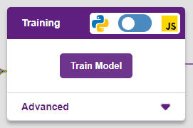
The accuracy of the model should increase over time. The x-axis of the graph shows the epochs, and the y-axis represents the accuracy at the corresponding epoch. Remember, the higher the reading in the accuracy graph, the better the model. The range of the accuracy is 0 to 1.
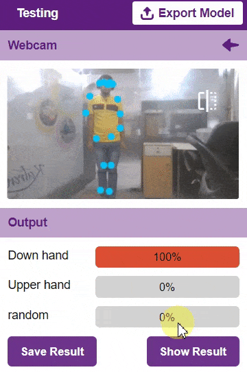
Testing the Model
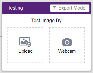
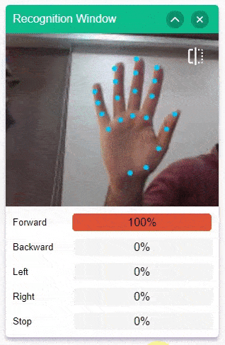
To test the model, simply enter the input values in the “Testing” panel and click on the “Predict” button.
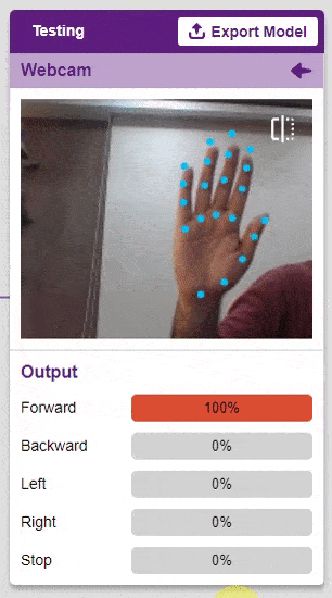
The model will return the probability of the input belonging to the classes.
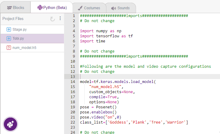
Export in Python Coding
Click on the “Export Model” button on the top right of the Testing box, and PictoBlox will load your model into the Python Coding Environment if you have opened the ML Environment in the Python Coding.
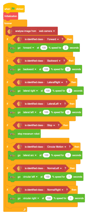
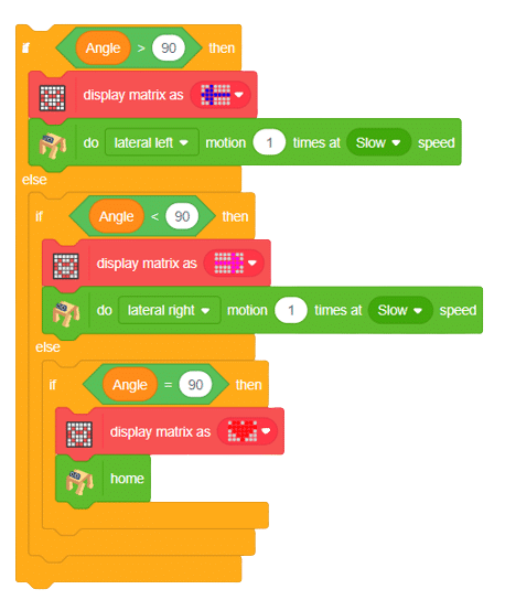
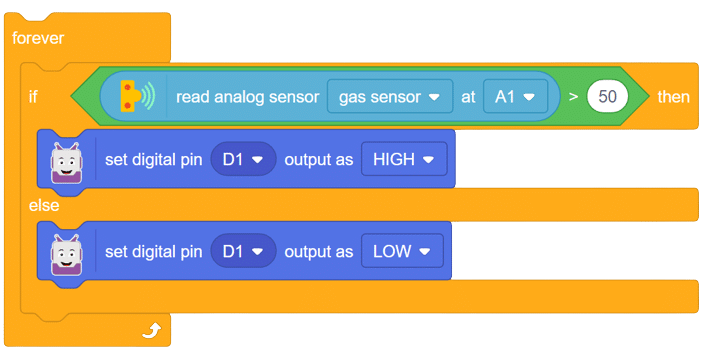
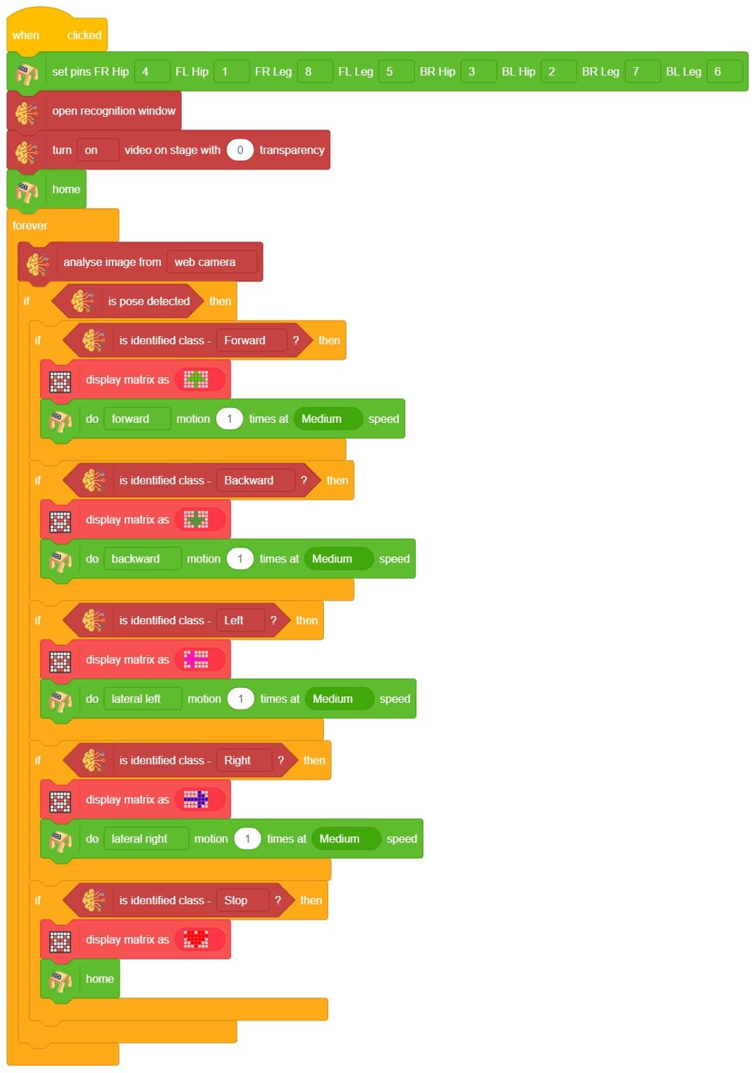
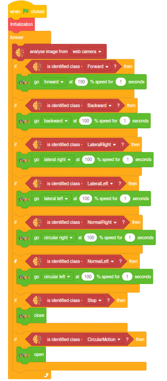
Logic
The mecanum will move according to the following logic:
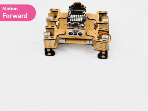
- If the detected class is “forward”, we will make the Mecanum move forward.
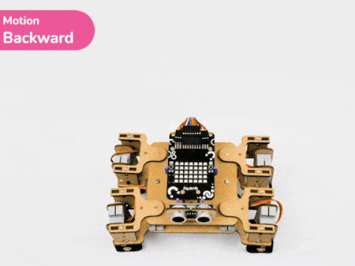
- When the backward gesture is detected – Mecanum will move backwards.
- When the Lateral Left gesture is detected – Mecanum will move towards the left direction laterally with the help of its omnidirectional wheels.
- When the Lateral Right gesture is detected – Mecanum will move towards the right direction laterally with the help of its omnidirectional wheels.
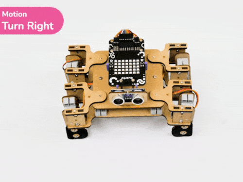
- When the Normal Right gesture is detected – Mecanum will rotate on a single point towards the right direction.
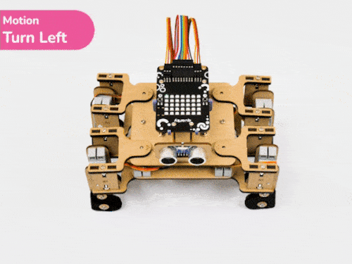
- When the Normal Left gesture is detected – Mecanum will rotate on a single point towards the left direction.
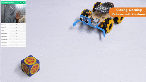
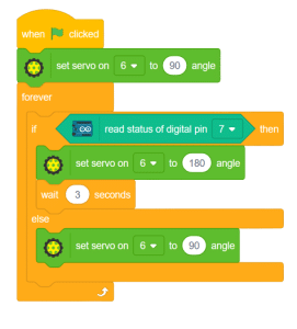
- When the “Stop” class gesture is detected, we will use the gripper functions of the Mecanum and Pick the object.
- When the “Circular Motion ” class is detected, we will use the gripper functions of the Mecanum and Drop the object by opening the arms of the gripper robot.
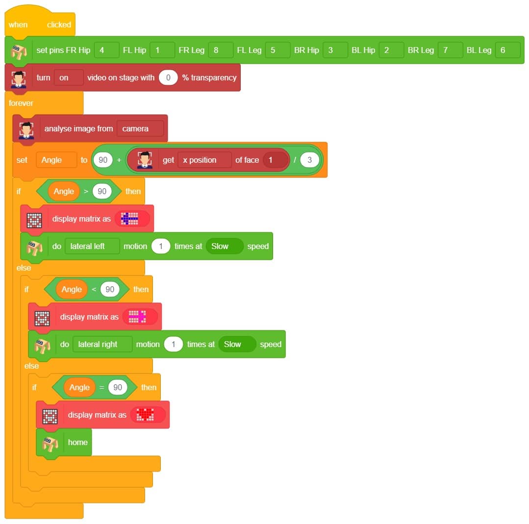
Code
Logical Code:
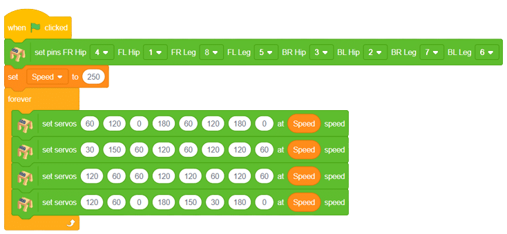
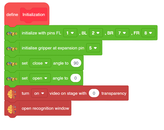
meca=Mecanum(1,2,7,8)
meca.initialisegripper(5)
meca.setcloseangle(90)
meca.setopenangle(0)

def runmecanum(predicted_class):
  if pose.ishanddetected():
    if predicted_class=="Forward":
      meca.runtimedrobot("forward",100,2)
    if predicted_class=="Backward":
      meca.runtimedrobot("backward",100,2)
    if predicted_class=="Stop":
      meca.closearm()
    if predicted_class=="LateralRight":
      meca.runtimedrobot("lateral right",100,2)
    if predicted_class=="LateralLeft":
      meca.runtimedrobot("lateral left",100,2)
    if predicted_class=="NormalRight":
      meca.runtimedrobot("circular right",100,1)
    if predicted_class=="NormalLeft":
      meca.runtimedrobot("circular left",100,1)
    if predicted_class=="CircularMotion":
      meca.openarm()
Final Code
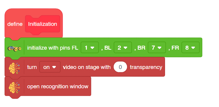
- We will create a custom function as shown above that will help us to control the Gripper Mecanum robot easily with the help of the Machine Learning model that we created.
- We will also initialize the gripper pins and the mecanum pins before writing the main function. We can also set the gripper angle for closing and opening of the gripper with the help of “setgripperangle()” function.
- We will also have to call the function at the last line of the code where we will call the function that we have created for the code to run properly.
####################imports####################
# Do not change

import numpy as np
import tensorflow as tf
import time

# Do not change
####################imports####################

#Following are the model and video capture configurations
# Do not change

model=tf.keras.models.load_model(
    "num_model.h5",
    custom_objects=None,
    compile=True,
    options=None)
pose = Posenet()                                                    # Initializing Posenet
pose.enablebox()                                                    # Enabling video capture box
pose.video("on",0)                                                  # Taking video input
class_list=['Forward','Backward','Stop','LateralRight','LateralLeft','NormalRight','NormalLeft','CircularMotion']                  # List of all the classes
meca=Mecanum(1,2,7,8)
meca.initialisegripper(5)
meca.setcloseangle(90)
meca.setopenangle(0)

def runmecanum(predicted_class):
  if pose.ishanddetected():
    if predicted_class=="Forward":
      meca.runtimedrobot("forward",100,2)
    if predicted_class=="Backward":
      meca.runtimedrobot("backward",100,2)
    if predicted_class=="Stop":
      meca.closearm()
    if predicted_class=="LateralRight":
      meca.runtimedrobot("lateral right",100,2)
    if predicted_class=="LateralLeft":
      meca.runtimedrobot("lateral left",100,2)
    if predicted_class=="NormalRight":
      meca.runtimedrobot("circular right",100,1)
    if predicted_class=="NormalLeft":
      meca.runtimedrobot("circular left",100,1)
    if predicted_class=="CircularMotion":
      meca.openarm()
# Do not change
###############################################

#This is the while loop block, computations happen here
# Do not change

while True:
  pose.analysehand()                                             # Using Posenet to analyse hand pose
  coordinate_xy=[]

    # for loop to iterate through 21 points of recognition
  for i in range(21):
    if(pose.gethandposition(1,i,0)!="NULL"  or pose.gethandposition(2,i,0)!="NULL"):
      coordinate_xy.append(int(240+float(pose.gethandposition(1,i,0))))
      coordinate_xy.append(int(180-float(pose.gethandposition(2,i,0))))
    else:
      coordinate_xy.append(0)
      coordinate_xy.append(0)

  coordinate_xy_tensor = tf.expand_dims(coordinate_xy, 0)        # Expanding the dimension of the coordinate list
  predict=model.predict(coordinate_xy_tensor)                    # Making an initial prediction using the model
  predict_index=np.argmax(predict[0], axis=0)                    # Generating index out of the prediction
  predicted_class=class_list[predict_index]                      # Tallying the index with class list
  print(predicted_class)
  runmecanum(predicted_class)
  # Do not change
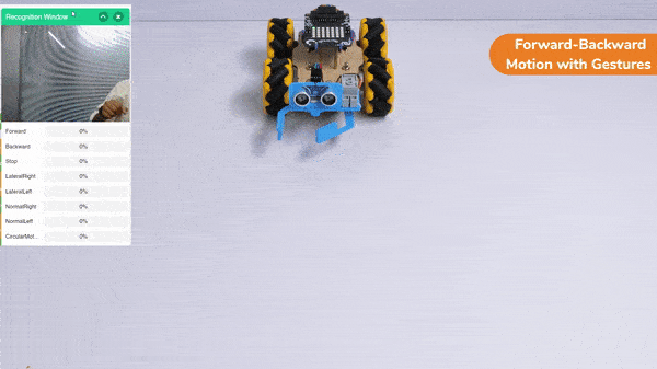
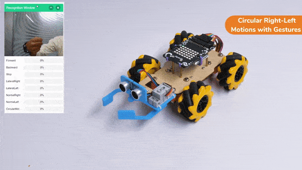
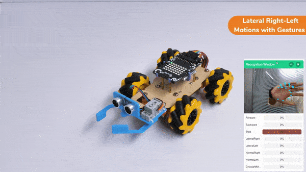
Output
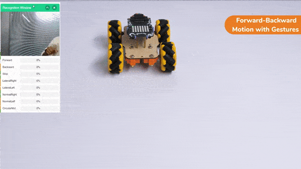
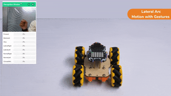
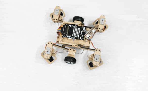
Forward-Backward Motion:
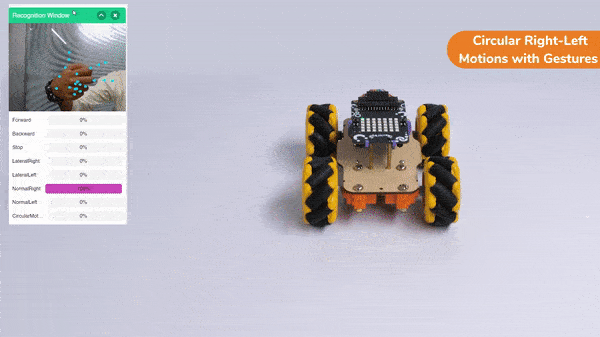
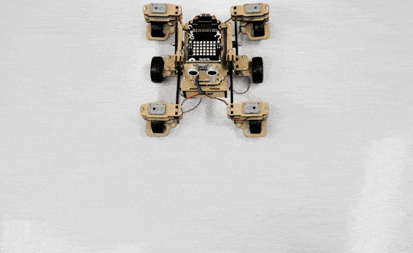
Circular Right-Left Motion:
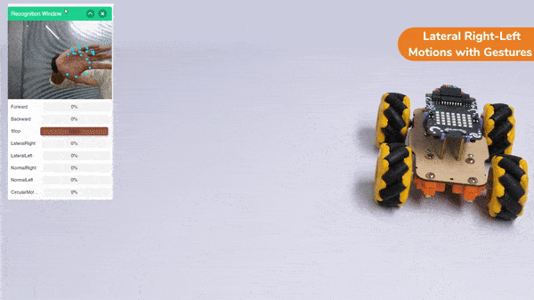
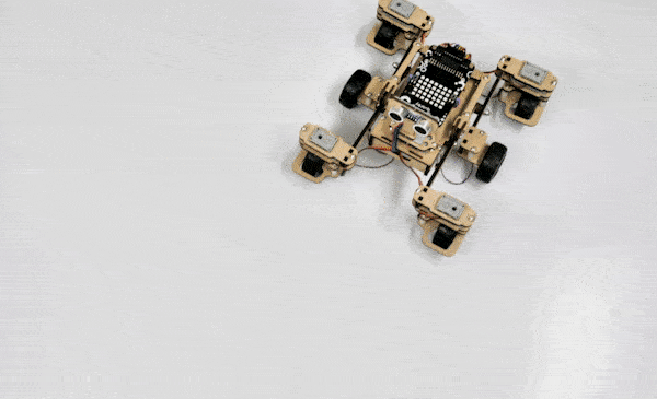
Lateral Right-Left Motions:
Gripper Mechanism with Hand Gestures:


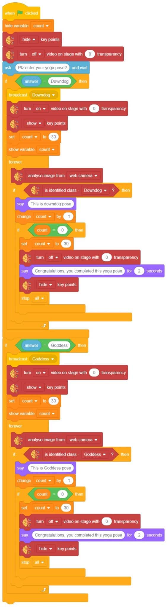
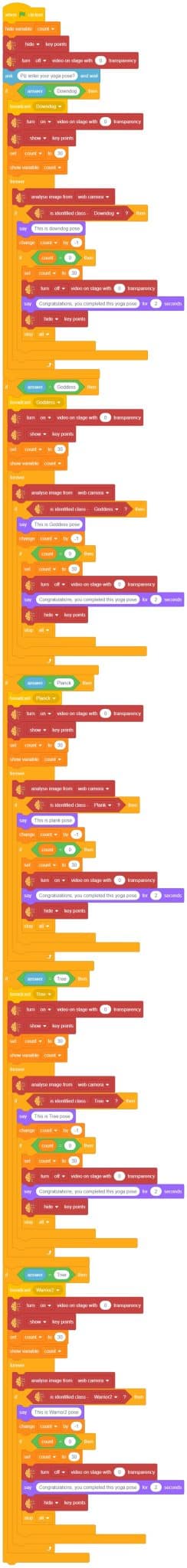
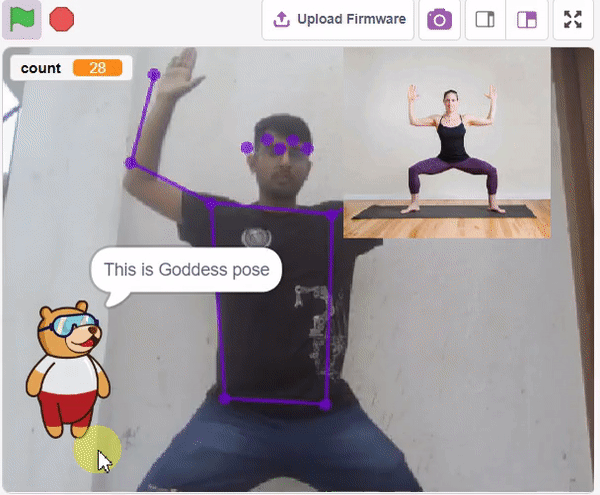


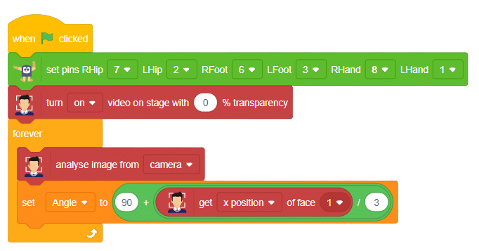


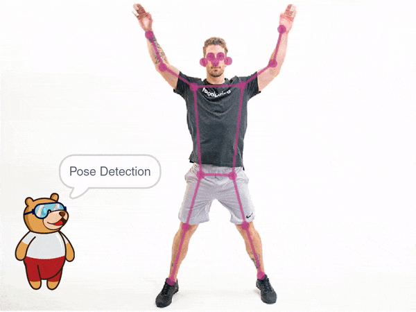
 The model works by analyzing your body position with the help of 17 data points.