Deprecated: Required parameter $query follows optional parameter $post in /var/www/html/wp-content/plugins/elementor-extras/modules/breadcrumbs/widgets/breadcrumbs.php on line 1215
Set PID Line Following Parameter - PictoBlox Block | Quarky Advance Line Following
Table of Contents
[BlocksExtension]

Warning: Undefined array key "pp_wrapper_link" in /var/www/html/wp-content/plugins/powerpack-elements/extensions/wrapper-link.php on line 194

Warning: Undefined array key "pp_wrapper_link_enable" in /var/www/html/wp-content/plugins/powerpack-elements/extensions/wrapper-link.php on line 196

Warning: Undefined array key "pp_custom_cursor_icon" in /var/www/html/wp-content/plugins/powerpack-elements/extensions/custom-cursor.php on line 350

Warning: Undefined array key "pp_custom_cursor_text" in /var/www/html/wp-content/plugins/powerpack-elements/extensions/custom-cursor.php on line 351

Warning: Undefined array key "pp_custom_cursor_target" in /var/www/html/wp-content/plugins/powerpack-elements/extensions/custom-cursor.php on line 352

Warning: Undefined array key "pp_custom_cursor_css_selector" in /var/www/html/wp-content/plugins/powerpack-elements/extensions/custom-cursor.php on line 353

Warning: Undefined array key "pp_custom_cursor_enable" in /var/www/html/wp-content/plugins/powerpack-elements/extensions/custom-cursor.php on line 355

Set PID Line Following Parameter

Description

Proportional, Integral, and Derivative (PID) functions are used to improve the feedback (analog inputs from the IR Sensors) to improve the robot’s movement.

1. Proportional (P) :  
This component enables the robot to make immediate, precise adjustments based on its distance from the line. If the robot drifts too far to the right, it will steer left, and if it veers too far to the left, it will steer right to correct its course.

2. Integral (I) : 
The integral component monitors how long the robot has been off the line. If the deviation persists for an extended time, this part applies a larger correction to bring the robot back on track more effectively.

3. Derivative (D) :
The derivative component anticipates future errors by analyzing the rate at which the robot drifts from the line. This ensures smooth, predictive adjustments, helping to prevent overshooting and maintain stability.

The control output is given by:
Control Output = Proportional + Integral + Derivative

So, the PID controller combines these three components to continuously adjust the robot’s movements, keeping it as close to the line as possible while moving smoothly and fast. A robot is always learning and fine-tuning its path to stay on track.
Think of it as a smart system that balances and corrects itself as it moves, ensuring it follows the line accurately. PID line followers are commonly used in robotics competitions and educational settings to teach about control systems and automation.

Note: If you initialize a Three IR line following, use Kp (propositional constant) >= 7 for a better result.

How does PID work in the Quarky Line Following?
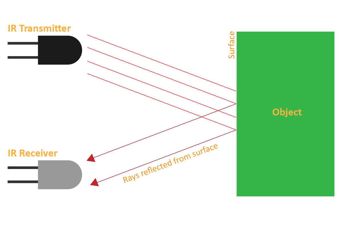
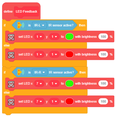
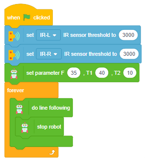
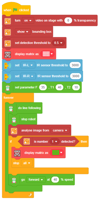
In Quarky’s “Do Line Following” Block/Python function, the system employs its two Infrared (IR) sensors, one on the left and another on the right, to navigate along a line.
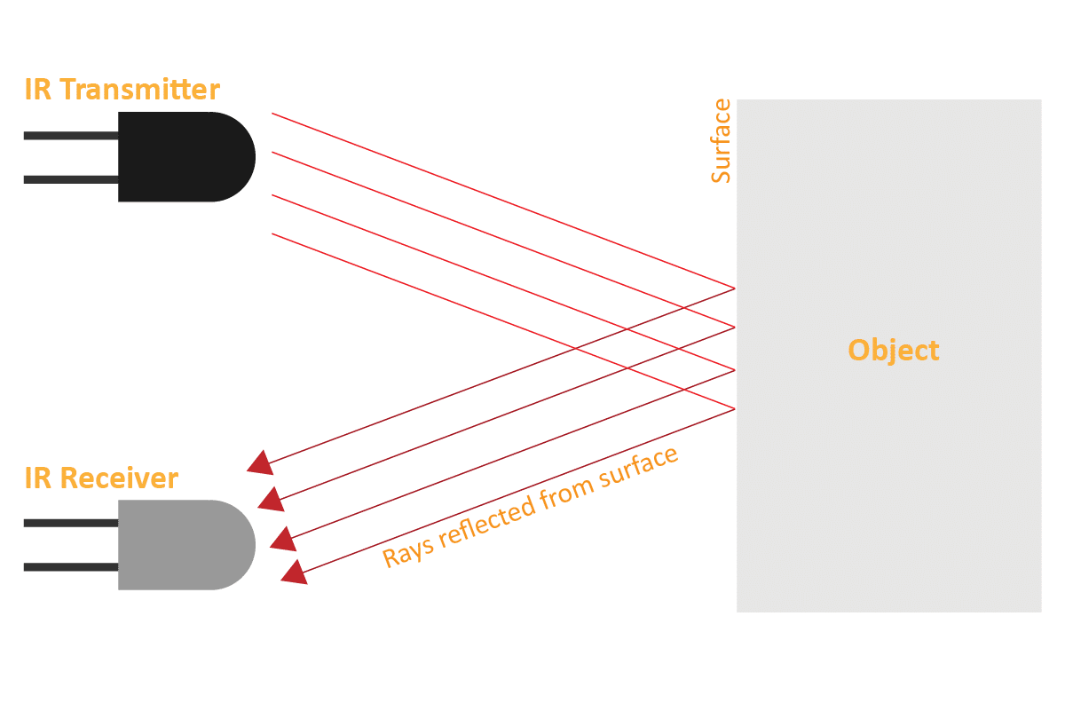
Let’s say the analog values registered by these sensors
on a white surface are
Left = 150
Right = 170

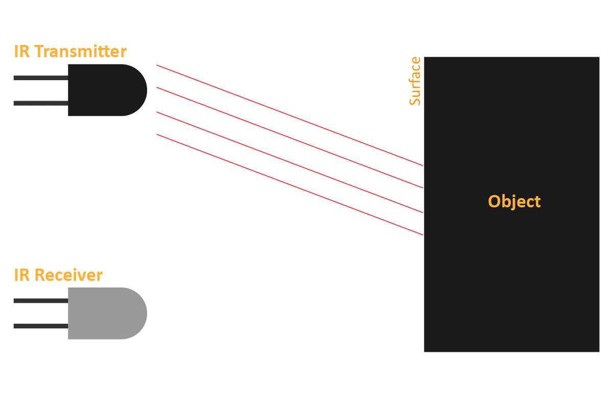
while on the black line, they read
Left = 820
Right = 750.

When the robot is shifted to the right, the left sensor is on the black line and the right one is on the white. At this point the reading of IR Sensors is
Left =  820
Right = 170,
The error is calculated as follows:

Error = (Left Sensor Value – Right Sensor Value)/10
= (820 – 170)/10
= 65

Proportional Only
For the PID (Proportional-Integral-Derivative) controller, the constants are set as follows:
Kp = 0.5, Ki = 0, and  Kd = 0.

The proportional term is then calculated.
Proportional = K_p *Error
= 0.5* 65
= 32 (approximately)

The control output is given by:
Control Output = Proportional + Integral + Derivative

In this case, both the integral and derivative terms are set to 0, so the control output simplifies to:
Control Output = 32 + 0 + 0
= 32

Subsequently, the motor speeds are adjusted based on the control output and the motor speed parameters.

Assuming base speed = 40, minimum speed = 0, and maximum speed = 80
The Left and Right motor speeds are computed as follows:

Left Motor Speed = Base Speed – Control Output
= 40 – 32
= 8

Right Motor Speed = Base Speed + Control Output
= 40 + 32
= 72

Proportional and Integral only
The integral term in the PID (Proportional-Integral-Derivative) controller addresses the accumulated past errors over time. If there has been a persistent error over time, the integral term gradually increases, helping to eliminate the accumulated error.

In a scenario where the robot is stuck and the robot’s tires are slipping due to the excessive weight of the robot and low battery, both sensors are placed on contrasting surfaces – the Left sensor on black and the Right sensor on white. Despite the challenging conditions, the proportional constant (Kp) comes into play, initially adjusting the motor speeds. As a result, the Left motor speed becomes 8, and the Right motor speed reaches 72.

When an integral term with a constant value (Ki = 0.01) is introduced into the control equation, the integral value is updated in each iteration:

I = I + error
I = 0 + 65 = 65

The control output, comprising proportional, integral, and derivative terms, is then computed as follows:
Control Output  = Proportional +Integral + Derivative
= (0.5 * 65) + (0.01 * 65) + 0
= 32.65
Left Motor Speed = 7.35
Right Motor Speed = 72.65

In the subsequent loop, the integral term is updated again:
I = I + error
I = 65 + 65 = 130

And the control output in the next iteration becomes:
Control Output = (0.5 * 65) + (0.01 * 130) + 0
= 33.3
Left Motor Speed = 6.7
Right Motor Speed = 73.3

Proportional, Integral, and Derivative
Derivative (D): The derivative term in the PID (Proportional-Integral-Derivative) controller anticipates future errors by assessing how fast the error is changing. It plays a crucial role in preventing overshooting or oscillations by slowing down the control action as the system approaches the setpoint.

In a small arena, when a robot needs to execute a significant turn or a U-turn, increasing the proportional constant (Kp) may result in excessive oscillations. To address this, the derivative term is introduced to control oscillations and overshooting.

Consider a scenario where the error is increased:
Error = (Left Sensor Value – Right Sensor Value)/10
=(930 – 170)/10
= 76

The derivative term is computed as:
D = Previous Error – Error
= 65 – 76
= -11

The control output, including proportional, integral, and derivative terms, is then calculated as follows:
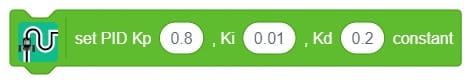
Kp = 0.5, Ki = 0.01, and  Kd = 0.2

Control Output = Proportional + Integral + Derivative
= (0.5 * 76) + (0.01 * 76) + (0.2 * -11)
= 38 + 0.76 – 2.2 = 36.56

Subsequently, the left and right motor speeds are adjusted:
Left Motor Speed = 3.44
Right Motor Speed = 76.56

In the subsequent loop, the integral term is updated, and the process repeats with a new error:
Error =  (600 – 170)/10
= 43

The integral term is updated:
I = I + Error
= 76 + 43
= 109

The derivative term for the new error is computed:
D = Previous Error – Error
= 76 – 43
= 33

The control output remains the same in this loop:
Control Output  = (0.5 * 43) + (0.01 * 109) + (0.2 * 33)
= 21.5 + 1.09 + 6.6
=29.19

Left Motor Speed = 10.81
Right Motor Speed = 69.19

This iterative process continues, with the derivative term helping to manage the robot’s response to changing errors, ultimately enhancing its stability.


Example

The example demonstrates how to calibrate the IR sensors to detect black lines on the white surface in Python Coding Environment.

Logic

An IR sensor consists of 2 LEDs: one which transmits the IR light and one which receives the IR light. When the IR rays are transmitted, they bounce from the nearest surface and get back to the receiver LED. That’s how an IR sensor detects an object.

But to detect colors, we depend on the number of rays the surface reflects:

  1. The dark surface will absorb more IR rays and as a result, the receiver will get fewer IR rays.
  2. White or shiny objects will absorb fewer IR rays and as a result, the receiver will get more IR rays.

We can get the sensor values in PictoBlox and based on that value we can estimate whether the surface is black or white.

  1. If the sensor detects the black line, its output value is increased. This means that the sensor is active.
  2. If it detects the white area, its output value decreases. This means that the sensor is inactive.

We will call the threshold value above which the sensor detects the black line. If the sensor value is less than the threshold, it means that the sensor hasn’t detected the line yet.

Alert: IR sensors DON’T work in sunlight. IR rays from the sun increase the overall threshold of the sensors therefore they stay active all time. A closed environment or nighttime is the place/time to work with your line following robot.

Code

sprite = Sprite('Tobi')

quarky = Quarky()

quarky.cleardisplay()
quarky.setirthreshold("IRL", 3000)
quarky.setirthreshold("IRR", 3000)

while True:
  if quarky.getirstate("IRL"):
    quarky.setled(1, 1, [0, 255, 0], 20)
  else:
    quarky.setled(1, 1, [255, 0, 0], 20)
  
  if quarky.getirstate("IRR"):
    quarky.setled(7, 1, [0, 255, 0], 20)
  else:
    quarky.setled(7, 1, [255, 0, 0], 20)


Calibrating the IR Sensors

Now, run the code by clicking the green flag and bringing the black line of the track close to the IR sensor. One of the following three conditions will happen:

  1. Your calibration value is HIGH: The black region will not be detected in this case. Reduce the calibration value.
  2. Your calibration value is LOW: The white region will not be detected in this case. Therefore, increase the calibration value.
  3. Your calibration value is OK. The white and black regions are detected accurately.

Now modify the script to add the detection value for the right IR sensor.

Output

Read More
The example demonstrates the various animation of the Quarky LED display in the Python Coding Environment.

Code

sprite = Sprite('Tobi')
quarky = Quarky()
import time

quarky.showemotion('happy')
time.sleep(1)
quarky.showemotion('angry')
time.sleep(1)
quarky.showemotion('crying')
time.sleep(1)
quarky.showemotion('super angry')
time.sleep(1)
quarky.showemotion('surprise')
time.sleep(1)
quarky.showemotion('basic')
time.sleep(1)
quarky.showemotion('love')
time.sleep(1)
quarky.showemotion('nerd')
time.sleep(1)
quarky.showemotion('reject')
time.sleep(1)
quarky.showemotion('wave')
time.sleep(1)
quarky.showemotion('thinking')
time.sleep(1)
quarky.showemotion('giggle')
time.sleep(1)
quarky.showemotion('disco')
time.sleep(1)

Output

Read More
The example demonstrates the various animation of the Quarky LED display in the Python Coding Environment.

Code

sprite = Sprite('Tobi')
quarky = Quarky()
import time

quarky.showanimation('happy')

quarky.showanimation('nerdy')

quarky.showanimation('thinking')

quarky.showanimation('angry')

quarky.showanimation('contempt')

quarky.showanimation('blink')

quarky.showanimation('fear')

quarky.showanimation('surprise')

quarky.showanimation('wink')

quarky.showanimation('wave')

quarky.showanimation('crying')

Output

Read More
The example demonstrates how to create a random colored LED pattern on Quarky in the Python Coding Environment.

Code

sprite = Sprite('Tobi')
quarky = Quarky()
import random

quarky.cleardisplay()

for x in range(1, 8):
  red = random.randrange(0, 255)
  green = random.randrange(0, 255)
  blue = random.randrange(0, 255)
  
  quarky.setled(x, 1, [red, green, blue], 100)

Output

Read More
The example demonstrates how to control the glowing LED using the keyboard keys in the Python Coding Environment.

Code

sprite = Sprite('Tobi')
quarky = Quarky()
import time

curr_x = 4
curr_y = 3
brightness = 50

quarky.cleardisplay()
quarky.setled(curr_x, curr_y, (0, 255, 0), brightness)

while True:
  
  if sprite.iskeypressed("up arrow"):
    curr_y = curr_y - 1
    quarky.setled(curr_x, curr_y + 1, (0, 0, 0), brightness)
    time.sleep(0.2)
    quarky.setled(curr_x, curr_y, (0, 255, 0), brightness)

  if sprite.iskeypressed("down arrow"):
    curr_y = curr_y + 1
    quarky.setled(curr_x, curr_y - 1, (0, 0, 0), brightness)
    time.sleep(0.2)
    quarky.setled(curr_x, curr_y, (0, 255, 0), brightness)
    
  if sprite.iskeypressed("left arrow"):
    curr_x = curr_x - 1
    quarky.setled(curr_x + 1, curr_y, (0, 0, 0), brightness)
    time.sleep(0.2)
    quarky.setled(curr_x, curr_y, (0, 255, 0), brightness)
    
  if sprite.iskeypressed("right arrow"):
    curr_x = curr_x + 1
    quarky.setled(curr_x - 1, curr_y, (0, 0, 0), brightness)
    time.sleep(0.2)
    quarky.setled(curr_x, curr_y, (0, 255, 0), brightness)
  
  time.sleep(0.2)
Read More
The example displays how we can display a custom pattern on the matrix by making a script to display a Traffic Light in the Python Coding Environment.

Code

sprite = Sprite('Tobi')
quarky=Quarky()

import time

quarky.setbrightness(15)

while True:
	quarky.drawpattern("bbbbbbbbbbbbbbbbbbbbbbbbbbbbbbbbbbb")
	time.sleep(5)
	quarky.showtext("2", [255,233,0])
	time.sleep(1)
	quarky.showtext("1", [255,233,0])
	time.sleep(1)
	quarky.drawpattern("ccccccccccccccccccccccccccccccccccc")
	time.sleep(5)
	quarky.showtext("2", [255,233,0])
	time.sleep(1)
	quarky.showtext("1", [255,233,0])
	time.sleep(1)

Output

Read More
The example demonstrates how to control the individual LEDs of the Quarky and run patterns using the loops in Python Coding Environment.

Code

sprite = Sprite('Tobi')
quarky = Quarky()

quarky.cleardisplay()
Y = 1
for i in range(0, 5):
  X = 1
  for i in range(0, Y):
    quarky.setled(X, Y, [101, 255, 0], 100)
    X += 1
  Y += 1

Output

Read More
The example demonstrates how to display scrolling text to make a name badge in the Python Coding Environment.

Code

sprite = Sprite('Tobi')
quarky=Quarky()

while True:
	quarky.showanimation("blink")
	quarky.showanimation("blink")
	quarky.showscrollingtext("Quarky", 2, [0, 255, 0])
	quarky.showscrollingtext("Robotics", 2, [0, 0, 255])

Output

Read More
The example demonstrates how to control the motion of the robot using keyboard keys.

Script

Output

Wirelessly-Controlled-Robot-1

Read More
Make-a-Square (1)
The example demonstrates how to make a square with Quarky robot.

Script

Note: You have to change the left turn time to make sure that the robot turns 90 degrees.

Output

Make-a-Square

Read More
The example demonstrates how to make the robot go in a circle with different motor speeds.

Script

Output

Read More
Robot Forward
The example demonstrates how the robot move forward, backward, left and right using motor direction control.

Forward

Robot Forward

Backward

Robot Backward

Left

Left Robot

Right

Right Robot

Read More
The example demonstrates how to make a vertical robot pet that senses the hand on the IR sensor and acts accordingly.

Script

Alert: You need to calibrate the IR sensor values to make this program run perfectly.

Output

Read More
The example demonstrates how to make a line follower robot with Quarky.

Logic

Script

Alert: You need to calibrate the IR sensor to get the best line detection by the robot. Also, you need to calibrate the speeds to make the robot follow the line correctly.

Output

Read More
The example demonstrates how to make a simplified line following a robot with Quarky.

Script

Alert: You need to calibrate the IR sensor to get the best line detection by the robot. Also, you need to calibrate the speeds to make the F, T1 and T2 speeds for the robot to follow the line correctly.

Output

Read More
The example demonstrates how to make a delivery robot that follows the line and stops when it reaches checkpoint 1.

Script

Alert: You need to calibrate the IR sensor to get the best line detection by the robot. Also, you need to calibrate the speeds to make the robot follow the line correctly.

Output


Read More
The example demonstrates how to calibrate the servo motor with Quarky.

The purpose of servo motor calibration is to align the angle of your servo motor properly.

Connecting Servo to Quarky

The Servo motor will be connected to the Quarky Servo Connector. There are two servo ports on Quarky. Always make sure that brown wire is on your left side.

Script

Put the Ultrasonic Assembly on the servo shaft.

Read More
The example demonstrates how to code the Quarky to make the servo sweep the perimeter.

Script

Output

Read More
The example demonstrates how to make a vertical robot pet that senses the hand on the IR sensor and acts accordingly in the Python Coding Environment.

Code

sprite = Sprite('Tobi')
quarky = Quarky()
import time

quarky.setorientation(2)
quarky.setirthreshold("IRL", 3000)
quarky.setirthreshold("IRR", 3000)

while True:
  if quarky.getirstate("IRL"):
    if quarky.getirstate("IRR"):
      quarky.cleardisplay()

    else:
      pass
      quarky.runrobot("LEFT", 100)
      time.sleep(0.3)
      quarky.stoprobot()

  else:
    pass
    if quarky.getirstate("IRR"):
      quarky.runrobot("RIGHT", 100)
      time.sleep(0.3)
      quarky.stoprobot()

    else:
      pass
      quarky.showemotion("happy")
      quarky.playsounduntildone("QuarkyIntro")

Output

Read More
The example demonstrates how to make a delivery robot that follows the line and stops when it reaches checkpoint 1 in the Python Coding Mode.

Code

sprite = Sprite('Tobi')
quarky = Quarky()
cards = RecognitionCards()

cards.video("on", 0)
cards.enablebox()
cards.setthreshold(0.5)

quarky.setirthreshold("IRL", 3000)
quarky.setirthreshold("IRR", 3000)
quarky.initializelinefollower(35, 40, 10)

quarky.drawpattern("aaaaaaaaaaaaaaaaaaaaaaaaaaaaaaaaaaa")

while True:
  if not (quarky.getirstate(35) and quarky.getirstate(34)):
    quarky.dolinefollowing()

  else:
    quarky.stoprobot()
    cards.analysecamera()

    if cards.isnumberdetected(1):
      quarky.drawpattern("ccccccccccccccccccccccccccccccccccc")
      break

    quarky.runrobot("FORWARD", 40)

Output

Read More
The example demonstrates how to code the Quarky to make the servo sweep the perimeter in the Python Coding Environment.

Code

sprite = Sprite('Tobi')
quarky = Quarky()
import time

Angle = 0
while True:
  for i in range(0, 18):
    Angle += 10
    moveservo("Servo 1", Angle)
    time.sleep(0.01)

  for i in range(0, 18):
    Angle += -10
    moveservo("Servo 1", Angle)
    time.sleep(0.01)

Output

Read More
The example demonstrates how to make a line follower robot with Quarky in the Python Coding Environment.

Code

sprite = Sprite('Tobi')
quarky = Quarky()

# User Defined Functions
def LED_Feedback():
  if quarky.getirstate("IRL"):
    quarky.setled(1, 1, [42, 255, 0], 100)

  else:
    pass
    quarky.setled(1, 1, [255, 0, 0], 100)

  if quarky.getirstate("IRR"):
    quarky.setled(7, 1, [42, 255, 0], 100)

  else:
    pass
    quarky.setled(7, 1, [255, 0, 0], 100)


quarky.setirthreshold("IRL", 3000)
quarky.setirthreshold("IRR", 3000)

while True:
  LED_Feedback()
  if (quarky.getirstate("IRL") and quarky.getirstate("IRR")):
    quarky.stoprobot()

  else:
    pass
    if quarky.getirstate("IRL"):
      quarky.runmotor("R", "FORWARD", 40)
      quarky.runmotor("L", "BACKWARD", 25)

    else:
      pass
      if quarky.getirstate("IRR"):
        quarky.runmotor("L", "FORWARD", 40)
        quarky.runmotor("R", "BACKWARD", 25)

      else:
        pass
        quarky.runrobot("FORWARD", 40)

Output

Read More
The example demonstrates how to make a simplified line following a robot with Quarky in the Python Coding Environment.

Code

sprite = Sprite('Tobi')
quarky = Quarky()

quarky.setirthreshold("IRL", 3000)
quarky.setirthreshold("IRR", 3000)
quarky.initializelinefollower(35, 40, 10)

while True:
  if not (quarky.getirstate(35) and quarky.getirstate(34)):
    quarky.dolinefollowing()

  else:
    quarky.stoprobot()

Output

Read More
The example demonstrates how to make the robot go in a circle with different motor speeds in the Python Coding Environment.

Code

sprite = Sprite('Tobi')
quarky = Quarky()

quarky.runmotor("L", "FORWARD", 20)
quarky.runmotor("R", "FORWARD", 100)

Output

Read More
The example demonstrates how to calibrate the servo motor with Quarky in Python Coding Environment.

The purpose of servo motor calibration is to align the angle of your servo motor properly.

Connecting Servo to Quarky

The Servo motor will be connected to the Quarky Servo Connector. There are two servo ports on Quarky. Always make sure that brown wire is on your left side.

Code

sprite = Sprite('Tobi')
quarky=Quarky()

quarky.moveservo("Servo 1", 90)


Put the Ultrasonic Assembly on the servo shaft.

Read More
The example demonstrates how to control the motion of the robot using keyboard keys in the Python Coding Environment.

Code

sprite = Sprite('Tobi')
quarky = Quarky()

while True:
  
  if sprite.iskeypressed("up arrow"):
    quarky.runrobot("FORWARD", 50)
  elif sprite.iskeypressed("down arrow"):
    quarky.runrobot("BACKWARD", 50)
  elif sprite.iskeypressed("left arrow"):
    quarky.runrobot("LEFT", 50)
  elif sprite.iskeypressed("right arrow"):
    quarky.runrobot("RIGHT", 50)
  else:
    quarky.stoprobot()

Output

Read More
Robot Forward
The example demonstrates how the robot moves forward, backward, left, and right using motor direction control in the Python Coding Environment.

Code

sprite = Sprite('Tobi')
quarky = Quarky()

# imported modules
import time

# User Defined Functions
def Forward():
  quarky.runmotor("L", "FORWARD", 100)
  quarky.runmotor("R", "FORWARD", 100)
  time.sleep(1)
  quarky.stopmotor("L")
  quarky.stopmotor("R")

def Backward():
  quarky.runmotor("L", "BACKWARD", 100)
  quarky.runmotor("R", "BACKWARD", 100)
  time.sleep(1)
  quarky.stopmotor("L")
  quarky.stopmotor("R")

def Left():
  quarky.runmotor("L", "BACKWARD", 100)
  quarky.runmotor("R", "FORWARD", 100)
  time.sleep(1)
  quarky.stopmotor("L")
  quarky.stopmotor("R")

def Right():
  quarky.runmotor("L", "FORWARD", 100)
  quarky.runmotor("R", "BACKWARD", 100)
  time.sleep(1)
  quarky.stopmotor("L")
  quarky.stopmotor("R")

Forward()
Backward()
Left()
Right()

Output

Robot Forward

Robot BackwardLeft RobotRight Robot

Read More
Make-a-Square (1)
The example demonstrates how to make a square with Quarky robot.

Code

sprite = Sprite('Tobi')
quarky = Quarky()

# imported modules
import time

for i in range(0, 4):
  quarky.runrobot("FORWARD", 100)
  time.sleep(1)
  quarky.stoprobot()
  quarky.runrobot("LEFT", 100)
  time.sleep(1.2)
  quarky.stoprobot()

Output

Make a Square

Read More
Buttons
The example demonstrates how to make the sprite movement with Quarky buttons.

Script

Output

Buttons

Read More
Buttons
The example demonstrates using the Quarky button to control the sprite using the hat block.

Script

Output

Buttons

Read More
All articles loaded
No more articles to load
[PictoBloxExtension]