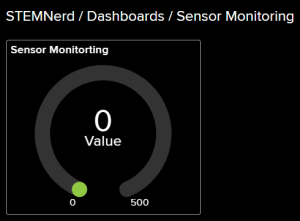
The block reports the selected field data from the last read request from ThingSpeak.
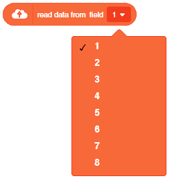
The block reports the selected field data from the last read request from ThingSpeak.
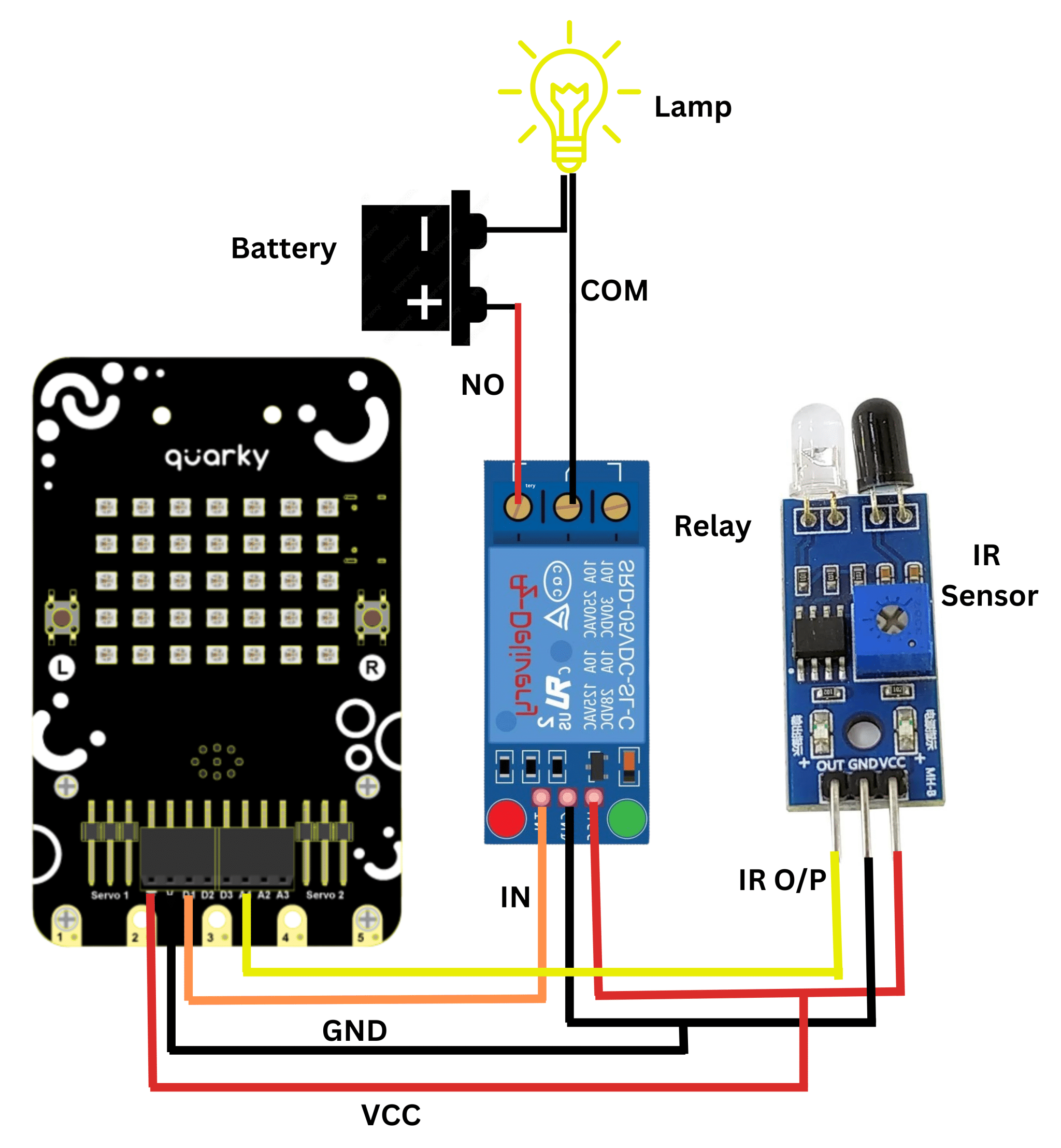
A relay is an electromagnetic switch that works on the principle of electromagnetic induction. A Realy is used to control the high voltage appliances using the microcontrollers. The relay has a primary side which is need to be connected to the controller and the secondary side is need to be connected to the load, for example, motor, light bulb, fan, etc. The primary side has 3 pins named as VCC, GND, and IN. secondary also has connections named as Common(COM), Normally Open(NO), and Normally Closed (NC).

In this example, we will be interfacing a relay with Quarky, We already know how to connect IR-Sensor with Quarky, and now we will be using ir sensor to trigger the relay. Let’s begin.
Script:
In this comprehensive introduction, you have learned about Relay and its interfacing with Quarky, the versatile microcontroller, and its potential in robotics and AI projects. Explore its various features, sensors, and plug-and-play functionality.

Steps:
Script

In this example, we look at how to establish and see if the Wi-Fi is connected to Quarky or not. The code will connect the Quarky to a specified Wi–Fi network and show a green status if the connection is successful, or a red status if the connection fails.


# imported modules
from quarky import *
import iot

# Create a Wi-Fi object
wifi = iot.wifi()

# Change the Wi-Fi Name and Password
wifi.connecttowifi("IoT", "12345678")

# Run the loop to check if the Wi-Fi is connected
while True:
  # Check if the Wi-Fi is connected
  if wifi.iswificonnected():
    # Draw a pattern on the quarky
    quarky.drawpattern("ccccccccccccccccccccccccccccccccccc")

  else:
    # Draw a different pattern on the quarky
    quarky.drawpattern("bbbbbbbbbbbbbbbbbbbbbbbbbbbbbbbbbbb")
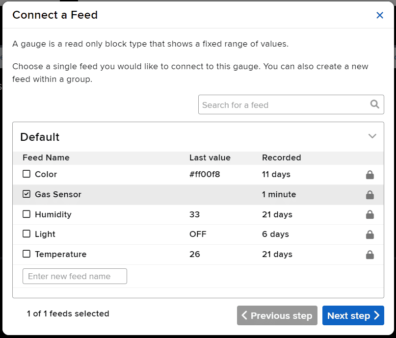
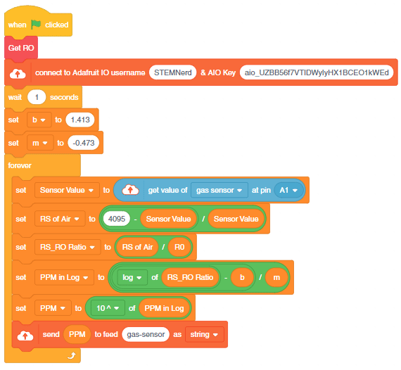
The project demonstrates how to interface the gas sensor to the Quarky and get the PPM reading. Later, we will create an air pollution monitoring system on Adafruit IO.
We will be using Adafruit IO for creating a switch on the cloud. Follow the instructions:
The relay has the following connections:
Gas sensors are designed to measure the concentration of gases in the environment. MQ2 gas sensor is suitable for detecting H2, LPG, CH4, CO, Alcohol, Smoke or Propane. Due to its high sensitivity and fast response time, measurements can be taken as soon as possible.

MQ-2 Gas Sensor Sensitivity Characteristics:
The graph tells us the concentration of a gas in part per million (ppm) according to the resistance ratio of the sensor (RS/R0).
For air, RS/R0 = 9.8 for the MQ2 gas sensor.
RS = [(Vin x RL) / Vout] - RL
We can simplify the above formula by omitting RL:
RS = (Vin - Vout) / Vout
From the graph, we can see that the resistance ratio in fresh air is constant:
RS / R0 = 9.8
To calculate R0 we will need to find the value of the RS in the fresh air using the above formula. This will be done by taking the analog average readings from the sensor and converting it to voltage. Then we will use the RS formula to find R0.
R0 = RS / 9.8
Let’s analyze the graph:
First of all, we will treat the lines as if they were linear. This way we can use one formula that linearly relates the ratio and the concentration. By doing so, we can find the concentration of a gas at any ratio value even outside of the graph’s boundaries. The formula we will be using is the equation for a line, but for a log-log scale. The formula for a line is:
y = mx + b
Where:
y: X value
x: X value
m: Slope of the line
b: Y intercept
For a log-log scale, the formula looks like this:
log(y) = m*log(x) + b
Continue writing text from here.
Okay, let’s find the slope. To do so, we need to choose 2 points from the graph.
In our case, we chose the points (200,1.6) and (10000,0.27) from the LPG line. The formula to calculate m is the following:
m = [log(y) - log(y0)] / [log(x) - log(x0)]
If we apply the logarithmic quotient rule we get the following:
m = log(y/y0) / log(x/x0)
Now we substitute the values for x, x0, y, and y0:
m = log(0.27/1.6) / log(10000/200)
m = -0.473
Now that we have m, we can calculate the y-intercept. To do so, we need to choose one point from the graph (once again from the LPG line). In our case, we chose (5000,0.46)
log(y) = m*log(x) + b
b = log(y) - m*log(x)
b = log(0.46) - (-0.473)*log(5000)
b = 1.413
Now that we have m and b, we can find the gas concentration for any ratio with the following formula:
log(x) = [log(y) - b] / m
However, in order to get the real value of the gas concentration according to the log-log plot we need to find the inverse log of x:
x = 10 ^ {[log(y) - b] / m}
In the table given below, you can find the value of m and b for different gases.
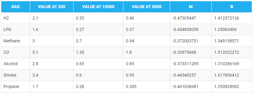
There are two steps to calculating PPM for the gas:
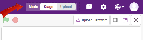
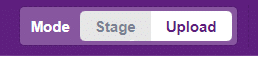
You can also make the project work independently of PictoBlox using the Upload Mode. For that switch to upload mode and replace the when green flag clicked block with when Quarky starts up the block.
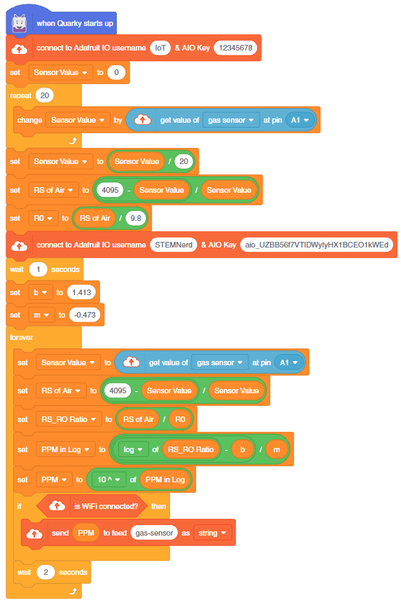
You can download the code from here: IoT- based Air Pollution Monitoring System – Upload Mode

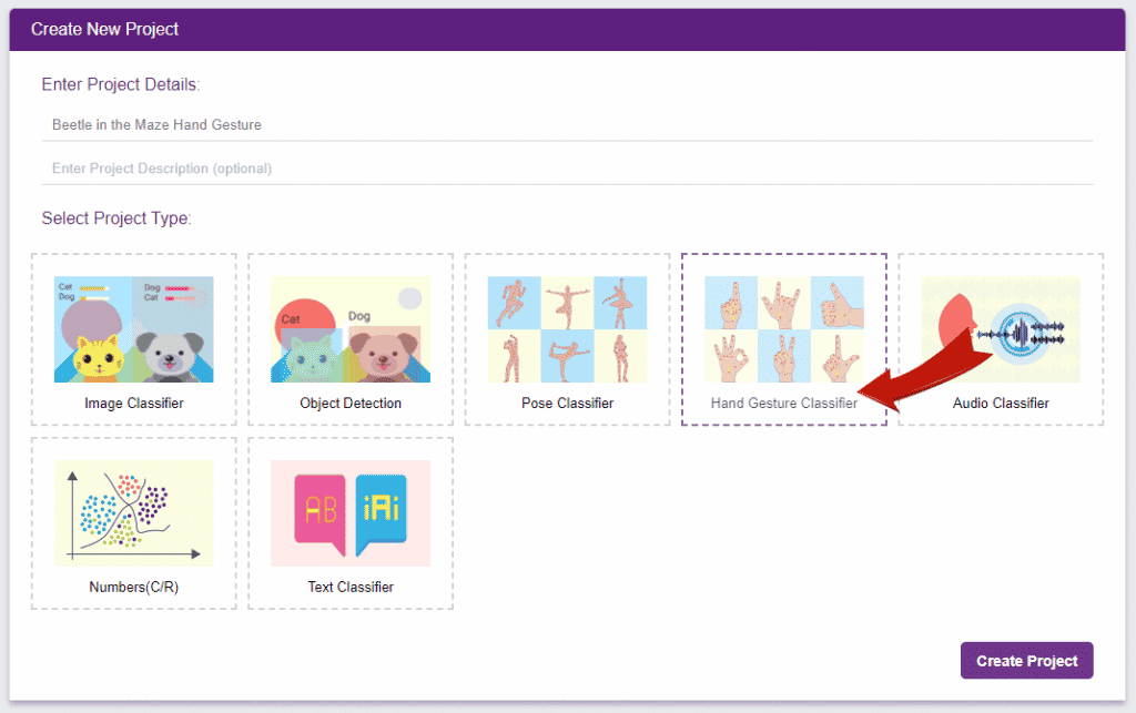
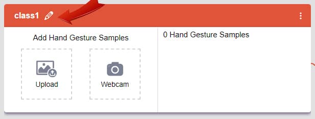
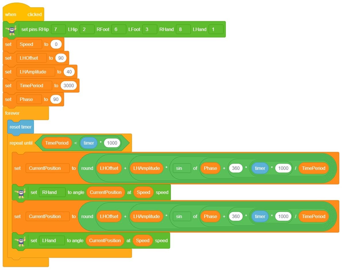
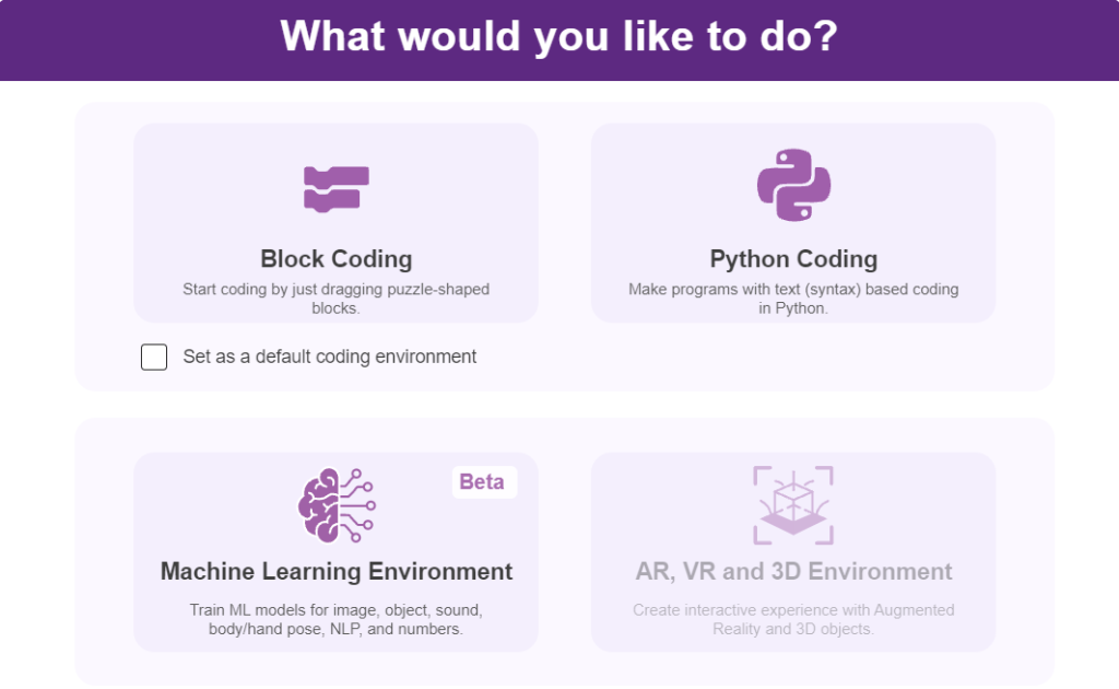
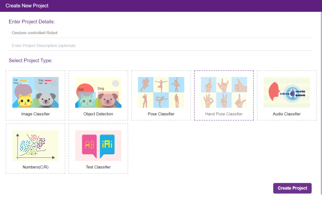
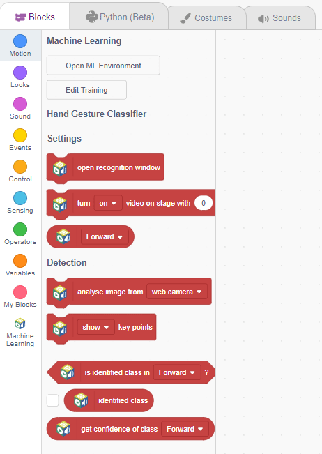
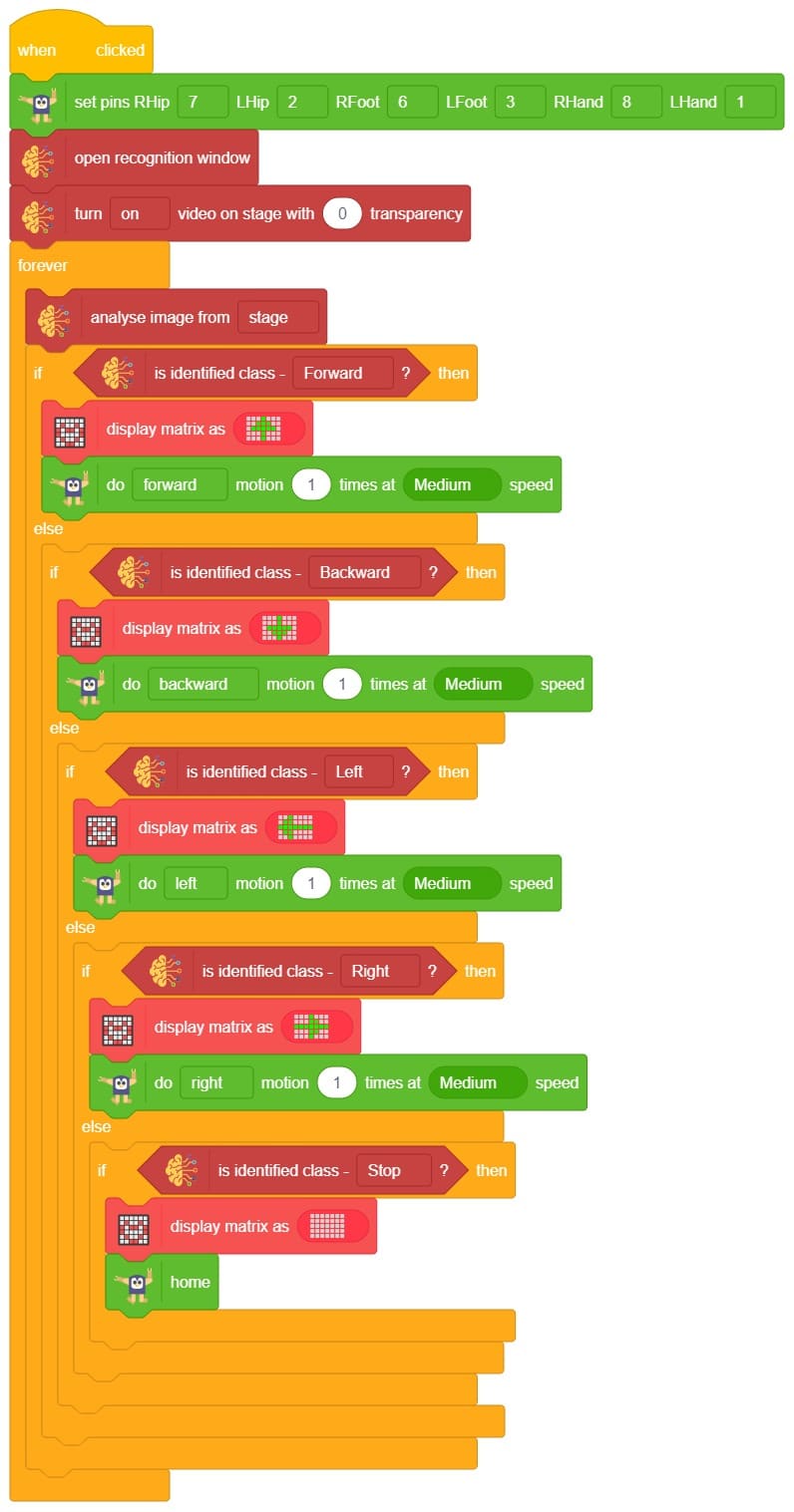
This project demonstrates how to use Machine Learning Environment to make a machine–learning model that identifies hand gestures and makes the humanoid move accordingly.
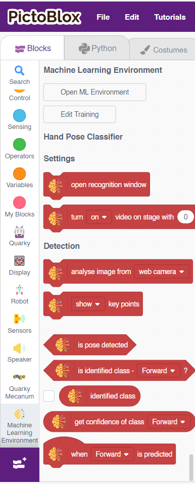
We are going to use the Hand Classifier of the Machine Learning Environment. The model works by analyzing your hand position with the help of 21 data points.
Follow the steps below:
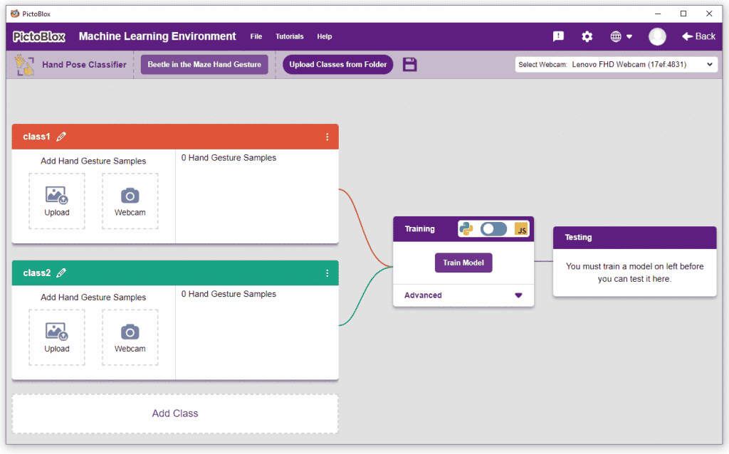
There are 2 things that you have to provide in a class:
You can perform the following operations to manipulate the data into a class.
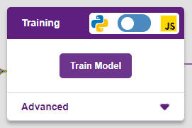
After data is added, it’s fit to be used in model training. In order to do this, we have to train the model. By training the model, we extract meaningful information from the hand pose, and that in turn updates the weights. Once these weights are saved, we can use our model to make predictions on data previously unseen.
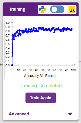
The accuracy of the model should increase over time. The x-axis of the graph shows the epochs, and the y-axis represents the accuracy at the corresponding epoch. Remember, the higher the reading in the accuracy graph, the better the model. The range of the accuracy is 0 to 1.
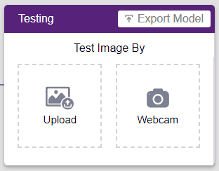
To test the model, simply enter the input values in the “Testing” panel and click on the “Predict” button.
The model will return the probability of the input belonging to the classes.
Click on the “Export Model” button on the top right of the Testing box, and PictoBlox will load your model into the Python Coding Environment if you have opened the ML Environment in Python Coding.
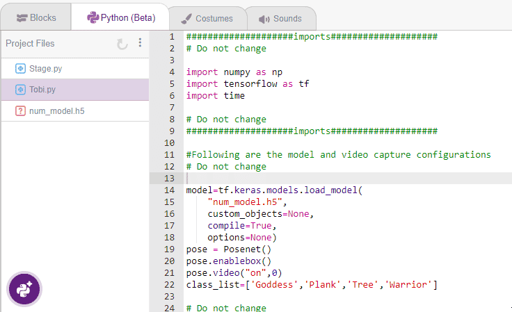
The following code appears in the Python Editor of the selected sprite.
####################imports####################
# Do not change

import numpy as np
import tensorflow as tf

sprite=Sprite('Tobi')
import time
quarky = Quarky()
import time

humanoid = Humanoid(7, 2, 6, 3, 8, 1)

# Do not change
####################imports####################

#Following are the model and video capture configurations
# Do not change

model=tf.keras.models.load_model(
    "num_model.h5",
    custom_objects=None,
    compile=True,
    options=None)
pose = Posenet()                                                    # Initializing Posenet
pose.enablebox()                                                    # Enabling video capture box
pose.video("on",0)                                                  # Taking video input
class_list=['forward','backward','left','right','stop']                  # List of all the classes
def runQuarky(predicted_class):
    if pose.ishanddetected():
      if predicted_class == "forward":
        humanoid.move("forward", 1000, 1)

      if predicted_class == "backward":
        humanoid.move("backward", 1000, 1)

      if predicted_class == "left":
        humanoid.move("left", 1000, 1)

      if predicted_class == "right":
        humanoid.move("right", 1000, 1)

      if predicted_class == "stop":
        humanoid.home()
    else:
      quarky.stoprobot()

# Do not change
###############################################

#This is the while loop block, computations happen here
# Do not change

while True:
  pose.analysehand()                                             # Using Posenet to analyse hand pose
  coordinate_xy=[]

    # for loop to iterate through 21 points of recognition
  for i in range(21):
    if(pose.gethandposition(1,i,0)!="NULL"  or pose.gethandposition(2,i,0)!="NULL"):
      coordinate_xy.append(int(240+float(pose.gethandposition(1,i,0))))
      coordinate_xy.append(int(180-float(pose.gethandposition(2,i,0))))
    else:
      coordinate_xy.append(0)
      coordinate_xy.append(0)

  coordinate_xy_tensor = tf.expand_dims(coordinate_xy, 0)        # Expanding the dimension of the coordinate list
  predict=model.predict(coordinate_xy_tensor)                    # Making an initial prediction using the model
  predict_index=np.argmax(predict[0], axis=0)                    # Generating index out of the prediction
  predicted_class=class_list[predict_index]                      # Tallying the index with class list
  print(predicted_class)
  runQuarky(predicted_class)
if pose.ishanddetected():
      if predicted_class == "forward":
        humanoid.move("forward", 1000, 1)

      if predicted_class == "backward":
        humanoid.move("backward", 1000, 1)

      if predicted_class == "left":
        humanoid.move("left", 1000, 1)

      if predicted_class == "right":
        humanoid.move("right", 1000, 1)

      if predicted_class == "stop":
        humanoid.home()
    else:
      quarky.stoprobot()

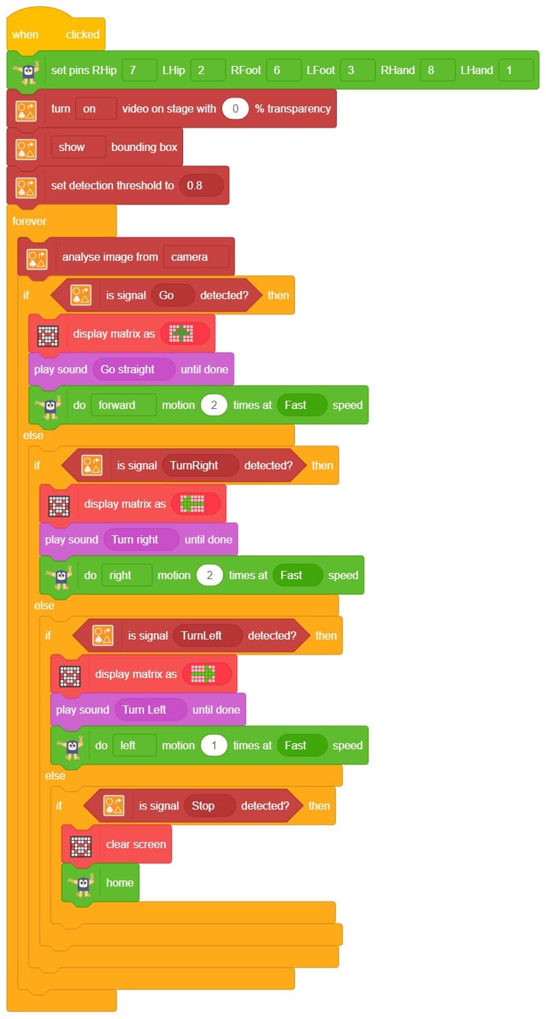
A sign detector Humanoid robot is a robot that can recognize and interpret certain signs or signals, such as hand gestures or verbal commands, given by a human. The robot uses sensors, cameras, and machine learning algorithms to detect and understand the sign, and then performs a corresponding action based on the signal detected.
These robots are often used in manufacturing, healthcare, and customer service industries to assist with tasks that require human-like interaction and decision-making.

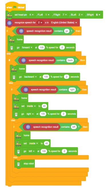
Learn how to code logic for speech recognized control of Mars Rover with this example block code. You will be able to direct your own Mars Rover easily by just speaking commands.
A speech recognized controlled Mars Rover robot is a robot that can recognize and interpret our speech, verbal commands, given by a human. The code uses the speech recognition model that will be able to record and analyze your speech given and react accordingly on the Mars Rover.
Speech recognition robots can be used in manufacturing and other industrial settings to control machinery, perform quality control checks, and monitor equipment.
They are also used to help patients with disabilities to communicate with their caregivers, or to provide medication reminders and other health-related information.
Main Code:
Forward-Backward Motions:
Right-Left Motions:

In this activity, we will control the Mecanum Gripper according to our needs using the Dabble application on our own Devices.
We will first understand how to operate Dabble and how to modify our code according to the requirements. The following image is the front page of the Dabble Application.
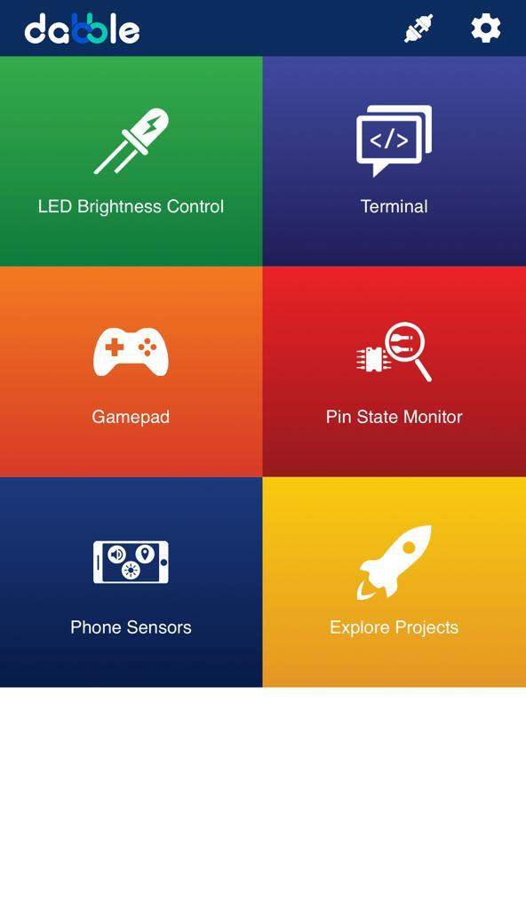
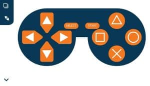
Select the Gamepad option from the Home Screen and we will then use the same gamepad to control our Mecanum Gripper.

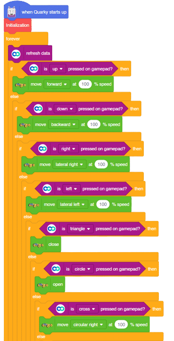
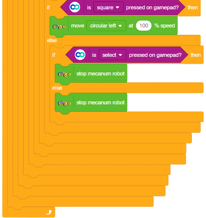
The following blocks represent the different functions that are created to control the Mecanum Gripper for different types of motions. We will use the arrow buttons to control the basic movements.( Forward, Backward, Lateral Left, Lateral Right ). We will use custom functions to control the gripper actions. We will use the Triangle button to close the gripper arms and the Circle button to open the gripper arms. We will use the Cross button to rotate to the right direction and we will use the Square button to rotate to the left direction. We can use the Select button to stop the Mecanum whenever possible.
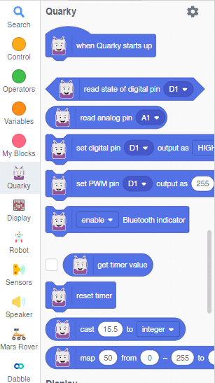
Note: You can always customize each and every function and button, and make your own activities easily. You will have to add the extensions of Mecanum and also of Dabble to access the blocks. To access the basic extensions required, make sure to select the Board as Quarky first.
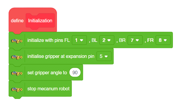
Initialization
Main Code
You will have to connect the Quarky with the Dabble Application on your device. Make sure Bluetooth is enabled on the device before connecting. Connect the Mecanum to the Dabble application after uploading the code. You will be able to connect by clicking on the plug option in the Dabble Application as seen below. Select that plug option and you will find your Quarky device. Connect by clicking on the respective Quarky.
Forward-Backward Motion:
Circular Right-Left Motion:
Lateral Right-Left Motion:
Gripper Mechanism:
In this activity, we will control the Mecanum Gripper according to our needs using the Dabble application on our own Devices.
We will first understand how to operate Dabble and how to modify our code according to the requirements. The following image is the front page of the Dabble Application.
Select the Gamepad option from the Home Screen and we will then use the same gamepad to control our Mecanum Gripper.
The following blocks represent the different functions that are created to control the Mecanum Gripper for different types of motions. We will use the arrow buttons to control the basic movements.( Forward, Backward, Lateral Left, Lateral Right ). We will use custom functions to control the gripper actions. We will use the Triangle button to close the gripper arms and the Circle button to open the gripper arms. We will use the Cross button to rotate to the right direction and we will use the Square button to rotate to the left direction. We can use the Select button to stop the Mecanum whenever possible.
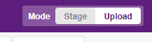
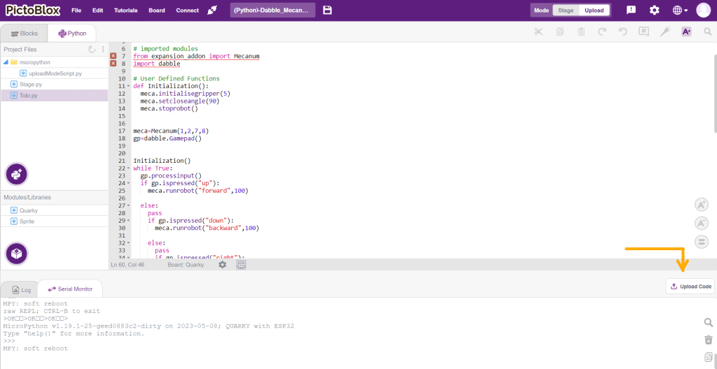
Note: You can always customize each and every function and button, and make your own activities easily. You will have to add the extensions of Mecanum and also of Dabble to access the functions. To access the basic extensions required, make sure to select the Board as Quarky first. Select the Python Coding Environment and on the top right click on the Upload Mode only for the code to work properly.
from quarky import *
# imported modules
from expansion_addon import Mecanum
import dabble

# User Defined Functions
def Initialization():
	meca.initialisegripper(5)
	meca.setcloseangle(90)
	meca.stoprobot()


meca=Mecanum(1,2,7,8)
gp=dabble.Gamepad()


Initialization()
while True:
	gp.processinput()
	if gp.ispressed("up"):
		meca.runrobot("forward",100)

	else:
		pass
		if gp.ispressed("down"):
			meca.runrobot("backward",100)

		else:
			pass
			if gp.ispressed("right"):
				meca.runrobot("lateral right",100)

			else:
				pass
				if gp.ispressed("left"):
					meca.runrobot("lateral left",100)

				else:
					pass
					if gp.ispressed("triangle"):
						meca.closearm()

					else:
						pass
						if gp.ispressed("circle"):
							meca.openarm()

						else:
							pass
							if gp.ispressed("cross"):
								meca.runrobot("circular right",100,1)

							else:
								pass
								if gp.ispressed("square"):
									meca.runrobot("circular left",100,1)

								else:
								  pass
								  if gp.ispressed("select"):
								    meca.stoprobot()


								  else:
									  pass
									  meca.stoprobot()
You will have to connect the Quarky with the Dabble Application on your device. Make sure Bluetooth is enabled on the device before connecting. Connect the Mecanum to the Dabble application after uploading the code. You will be able to connect by clicking on the plug option in the Dabble Application as seen below. Select that plug option and you will find your Quarky device. Connect by clicking on the respective Quarky.
Forward-Backward Motion:
Circular Right-Left Motion:
Lateral Right-Left Motion:
Gripper Mechanism:
Sign detection is being performed using a camera and a RecognitionCards object. The RecognitionCards object is set up with a threshold value and is enabled to draw a box around the detected object. The robot uses sensors, cameras, and machine learning algorithms to detect and understand the sign, and then performs a corresponding action based on the signal detected.
These robots are often used in manufacturing, healthcare, and customer service industries to assist with tasks that require human-like interaction and decision-making.
sprite = Sprite('Tobi')
quarky = Quarky()

import time
quad=Quadruped(4,1,8,5,3,2,7,6)

recocards = RecognitionCards()
recocards.video("on flipped")
recocards.enablebox()
recocards.setthreshold(0.6)
quad.home()
while True:
  recocards.analysecamera()
  sign = recocards.classname()
  sprite.say(sign + ' detected')

  if recocards.count() > 0:
    if 'Go' in sign:
      quarky.drawpattern("jjjijjjjjiiijjjiiiiijjjjijjjjjjijjj")
      quad.move("forward",1000,1)


    if 'Turn Left' in sign:
      quarky.drawpattern("jjjddjjjjjdddjdddddddjjjdddjjjjddjj")
      quad.move("lateral right",1000,1)


    if 'Turn Right' in sign:
      quarky.drawpattern("jjggjjjjgggjjjgggggggjgggjjjjjggjjj")
      quad.move("lateral left",1000,1)


    if 'U Turn' in sign:
      quarky.drawpattern("jjjbjjjjjjbjjjjbbbbbjjjbbbjjjjjbjjj")
      quad.move("backward",1000,1)


    else:
      quad.home()
A face-tracking robot is a type of robot that uses sensors and algorithms to detect and track human faces in real time. The robot’s sensors, such as cameras or infrared sensors, capture images or videos of the surrounding environment and use computer vision techniques to analyze the data and identify human faces. One of the most fascinating activities is face tracking, in which the Quadruped can detect a face and move its head in the same direction as yours. How intriguing it sounds, so let’s get started with the coding for a face-tracking Quadruped robot.
we will learn how to use face detection to control the movement of a Quadruped robot and how to incorporate external inputs into a program to create more interactive and responsive robotics applications.
sprite = Sprite('Tobi')
quarky=Quarky()

import time
import math
quad=Quadruped(4,1,8,5,3,2,7,6)

fd = FaceDetection()
fd.video("on", 0)
fd.enablebox()
fd.setthreshold(0.5)
time.sleep(1)
Angle=0
while True:
  fd.analysestage()
  for i in range(fd.count()):
    sprite.setx(fd.x(i + 1))
    sprite.sety(fd.y(i + 1))
    sprite.setsize(fd.width(i + 1))
    Angle=fd.width(i + 1)
    angle=int(float(Angle))
    if angle>90:
      quad.move("lateral right",1000,1)
    elif angle<90:
      quad.move("lateral left",1000,1)
    else: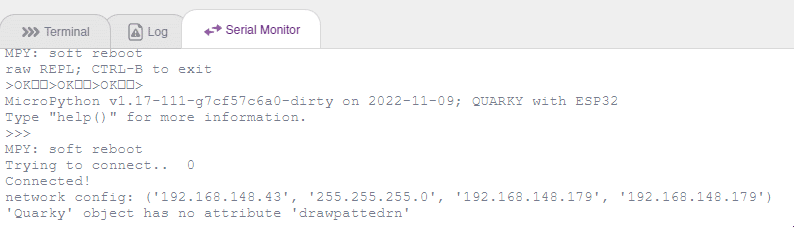
quad.home()Our next step is to check whether it is working right or not. Whenever your face will come in front of the camera, it should detect it and as you move to the right or left, the head of your Quadruped robot should also move accordingly.
![]()
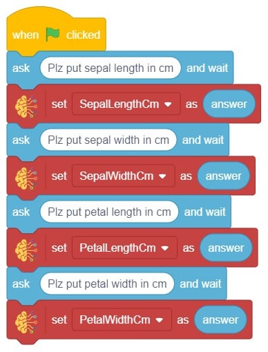
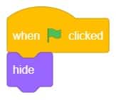
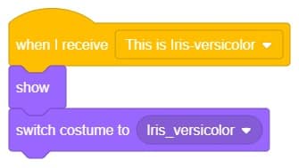
The idea is simple, we’ll add one image of each class in the “costume” column by making one new sprite which will we display on the stage according to input from user. we’ll also change name of the image according to iris type.


A pick-and-place robotic arm is a mechanical system designed to perform the task of picking up objects from one location and placing them in another. It consists of multiple segments connected, similar to a human arm, and is equipped with motors, sensors, and grippers.
The robotic arm is programmed to move in a precise and controlled manner. Various input methods, such as a computer interface or remote control can guide it. The arm uses its grippers to grasp objects securely, and then it can move them to a different location.
Pick-and-place robotic arms are commonly used in industries such as manufacturing, logistics, and assembly lines. They automate repetitive tasks that involve moving objects, saving time and reducing the risk of human error. With accuracy and efficiency, these robotic arms can handle a wide range of objects, from small components to larger items.
sprite = Sprite('Tobi')
roboticArm = RoboticArm(1,2,3,4)

roboticArm.calibrate(0, 0, 0)
roboticArm.setoffset(0,0)
roboticArm.setgripperangle(0,50)
roboticArm.sethome()
roboticArm.gripperaction("open")
roboticArm.movetoxyz(100,200,25,1000)
roboticArm.gripperaction("close")
roboticArm.movetoxyz(80,200,70,1000)
roboticArm.movetoxyz(-100,200,70,1000)
roboticArm.gotoinoneaxis(25,"Z",1000)
roboticArm.gripperaction("open")
roboticArm.movetoxyz(-100,200,100,1000)
roboticArm.gripperaction("close")
roboticArm.sethome()
Steps
Script
In this example, we will demonstrate how to control the door of the IoT House.
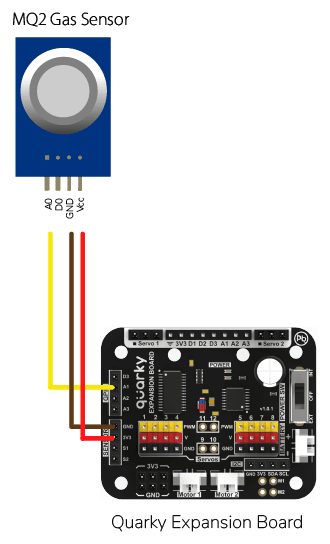
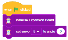
Connect the servo motor to the Quarky Expansion Board servo pin 5.
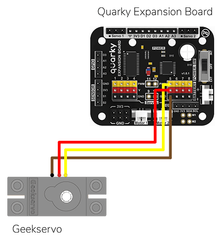
The door of the IoT House is controlled with a servo motor. You need to make the servo motor set to 0 angles before assembling the door. You can do it with the following script.
The following script makes the door closed by default and opens it for 1 second when the space key is pressed.
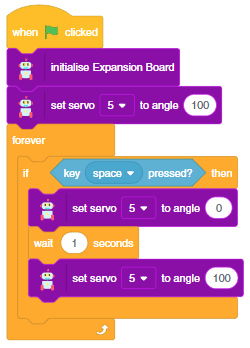
Press the space key to make the door open.
The project demonstrates how to interface the gas sensor to the Quarky and get the PPM (Parts Per Million) reading. Later, we will create an air pollution monitoring system on Adafruit IO.
We will be using Adafruit IO for creating a switch on the cloud. Follow the instructions:
The relay has the following connections:
Gas sensors are designed to measure the concentration of gases in the environment. MQ2 gas sensor is suitable for detecting H2, LPG, CH4, CO, Alcohol, Smoke or Propane. Due to its high sensitivity and fast response time, measurements can be taken as soon as possible.
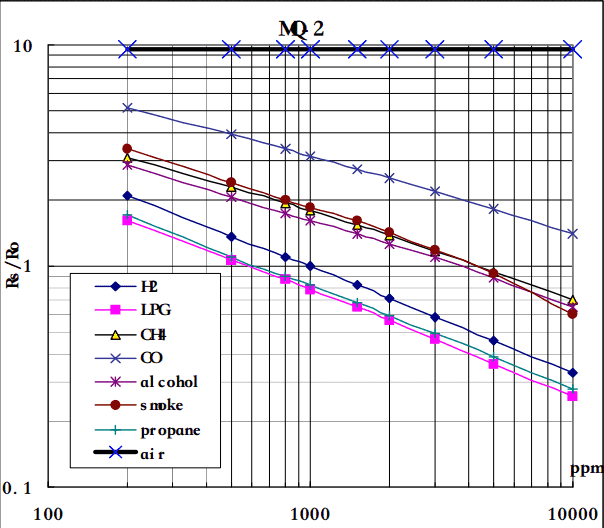
MQ-2 Gas Sensor Sensitivity Characteristics:
The graph tells us the concentration of a gas in part per million (ppm) according to the resistance ratio of the sensor (RS/R0).
For air, RS/R0 = 9.8 for the MQ2 gas sensor.
RS = [(Vin x RL) / Vout] - RL
We can simplify the above formula by omitting RL:
RS = (Vin - Vout) / Vout
From the graph, we can see that the resistance ratio in fresh air is constant:
RS / R0 = 9.8
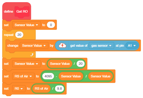
To calculate R0 we will need to find the value of the RS in the fresh air using the above formula. This will be done by taking the analog average readings from the sensor and converting it to voltage. Then we will use the RS formula to find R0.
R0 = RS / 9.8
Let’s analyze the graph:
First of all, we will treat the lines as if they were linear. This way we can use one formula that linearly relates the ratio and the concentration. By doing so, we can find the concentration of a gas at any ratio value even outside of the graph’s boundaries. The formula we will be using is the equation for a line, but for a log-log scale. The formula for a line is:
y = mx + b
Where:
y: X value
x: X value
m: Slope of the line
b: Y intercept
For a log-log scale, the formula looks like this:
log(y) = m*log(x) + b
Continue writing text from here.
Okay, let’s find the slope. To do so, we need to choose 2 points from the graph.
In our case, we chose the points (200,1.6) and (10000,0.27) from the LPG line. The formula to calculate m is the following:
m = [log(y) - log(y0)] / [log(x) - log(x0)]
If we apply the logarithmic quotient rule we get the following:
m = log(y/y0) / log(x/x0)
Now we substitute the values for x, x0, y, and y0:
m = log(0.27/1.6) / log(10000/200)
m = -0.473
Now that we have m, we can calculate the y-intercept. To do so, we need to choose one point from the graph (once again from the LPG line). In our case, we chose (5000,0.46)
log(y) = m*log(x) + b
b = log(y) - m*log(x)
b = log(0.46) - (-0.473)*log(5000)
b = 1.413
Now that we have m and b, we can find the gas concentration for any ratio with the following formula:
log(x) = [log(y) - b] / m
However, in order to get the real value of the gas concentration according to the log-log plot we need to find the inverse log of x:
x = 10 ^ {[log(y) - b] / m}
In the table given below, you can find the value of m and b for different gases.
There are two steps to calculating PPM for the gas:
#Importing the time and math modules to use later on in the code.
import time
import math
#Creating a Quarky object called 'quarky'.
quarky = Quarky()
#Creating an IoTHouse object called 'house' and an AdaIO object called 'adaio'.
house = IoTHouse()
adaio = AdaIO()
#Connecting the AdaIO object to Adafruit IO using a username and key.
adaio.connecttoadafruitio("STEMNerd", "aio_UZBB56f7VTIDWyIyHX1BCEO1kWEd")
#Initializing Sensor_Value to 0.1
Sensor_Value = 0.1
#Looping through 20 times to get the Sensor_Value
for i in range(0, 20):
Sensor_Value += house.ldrvalue("A1")
#Getting the average of the Sensor_Value
Sensor_Value = (Sensor_Value / 20)
#Getting the RS_of_Air from the Sensor_Value
RS_of_Air = ((4095 - Sensor_Value) / Sensor_Value)
#Getting the R0 from the RS_of_Air
R0 = (RS_of_Air / 9.8)
#Making the program wait for 1 second
time.sleep(1)
#Initializing b to 1.413 and m to -0.473
b = 1.413
m = -0.473
#A loop that will run forever
while True:
#Getting the Sensor_Value from the house
Sensor_Value = house.ldrvalue("A1")
#Making sure that Sensor_Value is not equal to 0
if Sensor_Value != 0:
#Getting the RS_of_Air from the Sensor_Value
RS_of_Air = ((4095 - Sensor_Value) / Sensor_Value)
#Getting the RS_RO_Ratio from the RS_of_Air and R0
RS_RO_Ratio = (RS_of_Air / R0)
#Getting the PPM_in_Log from the RS_RO_Ratio, b and m
PPM_in_Log = (((math.log(RS_RO_Ratio)) - b) / m)
#Getting the PPM from the PPM_in_Log
PPM = (pow(10, PPM_in_Log))
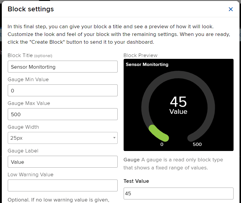
#Creating data with the AdaIO object called 'gas-sensor'
adaio.createdata("gas-sensor", PPM)
#Making the program wait for 2 seconds
time.sleep(2)
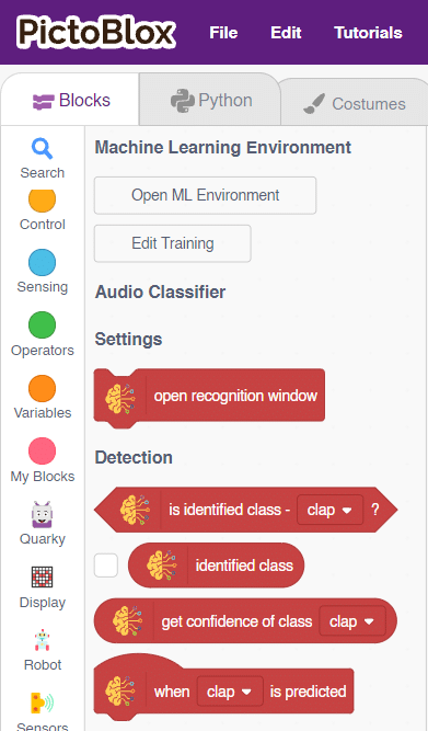
In this activity, we will use the Machine Learning Environment of the Pictoblox Software. We will use the Audio Classifier of the Machine Learning Environment and create our custom sounds to control the Mars Rover.
Follow the steps below to create your own Audio Classifier Model:
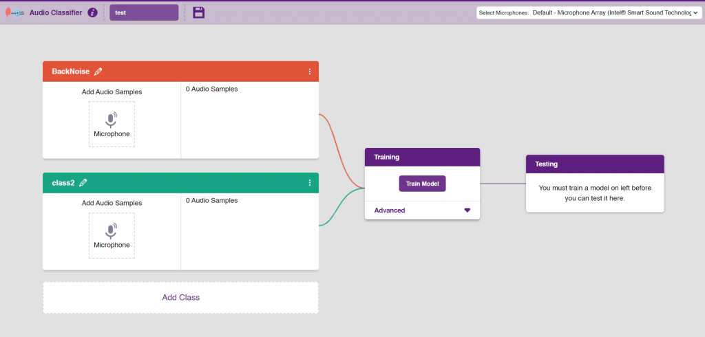
Note: You can add more classes to the projects using the Add Class button.
You can perform the following operations to manipulate the data into a class.
Note: You will only be able to change the class name in the starting before adding any audio samples. You will not be able to change the class name after adding the audio samples in the respective class.
After data is added, it’s fit to be used in model training. In order to do this, we have to train the model. By training the model, we extract meaningful information from the hand pose, and that in turn updates the weights. Once these weights are saved, we can use our model to make predictions on data previously unseen.
The accuracy of the model should increase over time. The x-axis of the graph shows the epochs, and the y-axis represents the accuracy at the corresponding epoch. Remember, the higher the reading in the accuracy graph, the better the model. The range of the accuracy is 0 to 1.
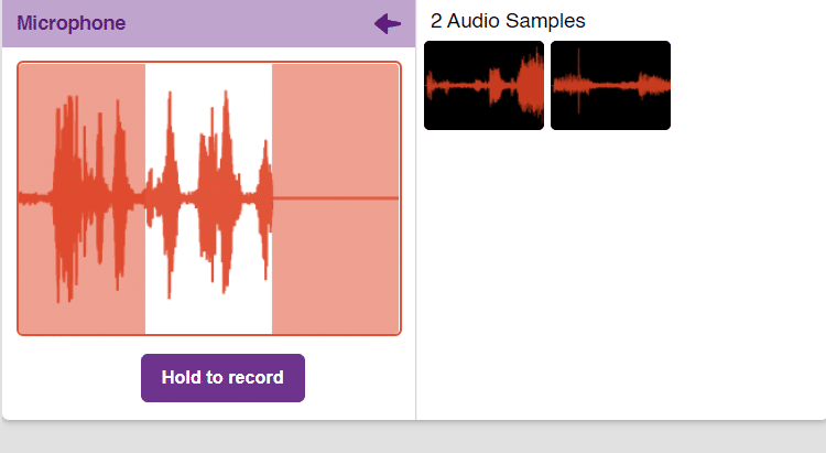
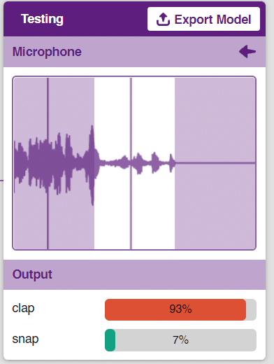
To test the model simply, use the microphone directly and check the classes as shown in the below image:
You will be able to test the difference in audio samples recorded from the microphone as shown below:
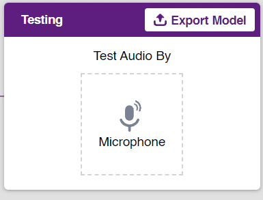
Click on the “Export Model” button on the top right of the Testing box, and PictoBlox will load your model into the Block Coding Environment if you have opened the ML Environment in the Block Coding.
The Mars Rover will move according to the following logic:
Note: You can add even more classes with different types of differentiating sounds to customize your control. This is just a small example from which you can build your own Sound Based Controlled Mars Rover in a very easy stepwise procedure.

The hand-controlled motion refers to the ability to control the movement of an object using hand gestures or motions. This can be accomplished through the use of various technologies, such as sensors or motion tracking devices, that detect the movements of the hand and translate them into commands that control the motion of the object.
Hand-controlled motion has a wide range of applications, including in virtual reality and gaming, robotics, prosthetics, and assistive technologies for individuals with disabilities. By allowing for intuitive and natural control of motion, hand-controlled motion can enhance the user’s experience and increase their ability to interact with and manipulate the world around them.

In this activity, we will try to create a new Machine Learning model that will be able to identify and detect different types of hand poses and that can help us to control the Mecanum Pick and Place Robot. This activity can be quite fun and by knowing the process, you can develop your own customized hand pose classifier model easily!
We will use the same model that we have created in the previous Hand Pose Controlled Mecanum model to avoid any misdirection and confusion.
Note: You can always create your own model and use it to perform any type of functions as per your choice. This example proves the same point and helps you understand well the concept of Machine Learning models and environment.
Follow the steps below:
There are 2 things that you have to provide in a class:
You can perform the following operations to manipulate the data into a class.
After data is added, it’s fit to be used in model training. In order to do this, we have to train the model. By training the model, we extract meaningful information from the hand pose, and that in turn updates the weights. Once these weights are saved, we can use our model to make predictions on data previously unseen.
The accuracy of the model should increase over time. The x-axis of the graph shows the epochs, and the y-axis represents the accuracy at the corresponding epoch. Remember, the higher the reading in the accuracy graph, the better the model. The range of the accuracy is 0 to 1.
To test the model, simply enter the input values in the “Testing” panel and click on the “Predict” button.
The model will return the probability of the input belonging to the classes.
Click on the “Export Model” button on the top right of the Testing box, and PictoBlox will load your model into the Block Coding Environment if you have opened the ML Environment in the Block Coding.
The mecanum will move according to the following logic:
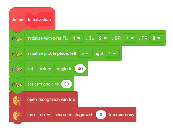
Initialization
Main Code
Forward-Backward Motion:
Circular Right-Left Motion:
Lateral Right-Left Motion:
Pick and Place Mechanism with Hand Pose:

In this activity, we will try to create a new Machine Learning model that will be able to identify and detect different types of hand poses and that can help us to control the Mecanum Pick and Place Robot. This activity can be quite fun and by knowing the process, you can develop your own customized hand pose classifier model easily!
We will use the same model that we have created in the previous Hand Pose Controlled Mecanum model to avoid any misdirection and confusion.
Note: You can always create your own model and use it to perform any type of functions as per your choice. This example proves the same point and helps you understand well the concept of Machine Learning models and environment.
Follow the steps below:
There are 2 things that you have to provide in a class:
You can perform the following operations to manipulate the data into a class.
After data is added, it’s fit to be used in model training. In order to do this, we have to train the model. By training the model, we extract meaningful information from the hand pose, and that in turn updates the weights. Once these weights are saved, we can use our model to make predictions on data previously unseen.
The accuracy of the model should increase over time. The x-axis of the graph shows the epochs, and the y-axis represents the accuracy at the corresponding epoch. Remember, the higher the reading in the accuracy graph, the better the model. The range of the accuracy is 0 to 1.
To test the model, simply enter the input values in the “Testing” panel and click on the “Predict” button.
The model will return the probability of the input belonging to the classes.
Click on the “Export Model” button on the top right of the Testing box, and PictoBlox will load your model into the Python Coding Environment if you have opened the ML Environment in the Python Coding.
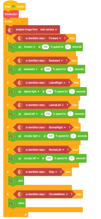
The mecanum will move according to the following logic:
Logical Code
meca=Mecanum(1,2,7,8)
meca.initialisepickplace(5,4)
meca.setpickangle(40)
meca.setarmangle(90)

def runmecanum(predicted_class):
  if pose.ishanddetected():
    if predicted_class=="Forward":
      meca.runtimedrobot("forward",100,2)
    if predicted_class=="Backward":
      meca.runtimedrobot("backward",100,2)
    if predicted_class=="Stop":
      meca.pick()
    if predicted_class=="LateralRight":
      meca.runtimedrobot("lateral right",100,2)
    if predicted_class=="LateralLeft":
      meca.runtimedrobot("lateral left",100,2)
    if predicted_class=="NormalRight":
      meca.runtimedrobot("circular right",100,1)
    if predicted_class=="NormalLeft":
      meca.runtimedrobot("circular left",100,1)
    if predicted_class=="CircularMotion":
      meca.place()
Final Code
####################imports####################
# Do not change

import numpy as np
import tensorflow as tf
import time

# Do not change
####################imports####################

#Following are the model and video capture configurations
# Do not change

model=tf.keras.models.load_model(
    "num_model.h5",
    custom_objects=None,
    compile=True,
    options=None)
pose = Posenet()                                                    # Initializing Posenet
pose.enablebox()                                                    # Enabling video capture box
pose.video("on",0)                                                  # Taking video input
class_list=['Forward','Backward','Stop','LateralRight','LateralLeft','NormalRight','NormalLeft','CircularMotion']                  # List of all the classes
meca=Mecanum(1,2,7,8)
meca.initialisepickplace(5,4)
meca.setpickangle(40)
meca.setarmangle(90)

def runmecanum(predicted_class):
  if pose.ishanddetected():
    if predicted_class=="Forward":
      meca.runtimedrobot("forward",100,2)
    if predicted_class=="Backward":
      meca.runtimedrobot("backward",100,2)
    if predicted_class=="Stop":
      meca.pick()
    if predicted_class=="LateralRight":
      meca.runtimedrobot("lateral right",100,2)
    if predicted_class=="LateralLeft":
      meca.runtimedrobot("lateral left",100,2)
    if predicted_class=="NormalRight":
      meca.runtimedrobot("circular right",100,1)
    if predicted_class=="NormalLeft":
      meca.runtimedrobot("circular left",100,1)
    if predicted_class=="CircularMotion":
      meca.place()

# Do not change
###############################################

#This is the while loop block, computations happen here
# Do not change

while True:
  pose.analysehand()                                             # Using Posenet to analyse hand pose
  coordinate_xy=[]

    # for loop to iterate through 21 points of recognition
  for i in range(21):
    if(pose.gethandposition(1,i,0)!="NULL"  or pose.gethandposition(2,i,0)!="NULL"):
      coordinate_xy.append(int(240+float(pose.gethandposition(1,i,0))))
      coordinate_xy.append(int(180-float(pose.gethandposition(2,i,0))))
    else:
      coordinate_xy.append(0)
      coordinate_xy.append(0)

  coordinate_xy_tensor = tf.expand_dims(coordinate_xy, 0)        # Expanding the dimension of the coordinate list
  predict=model.predict(coordinate_xy_tensor)                    # Making an initial prediction using the model
  predict_index=np.argmax(predict[0], axis=0)                    # Generating index out of the prediction
  predicted_class=class_list[predict_index]                      # Tallying the index with class list
  print(predicted_class)
  runmecanum(predicted_class)
  # Do not change
Forward-Backward Motion:
Circular Right-Left Motion:
Lateral Right-Left Motion:
Pick and Place Mechanism with Hand Pose:
####################imports####################
import numpy as np
import tensorflow as tf
sprite=Sprite('Tobi')
sprite1 = Sprite('Iris-versicolor')
sprite1.hide()
####################imports####################
model= tf.keras.models.load_model(
"num_model.h5",
custom_objects=None,
compile=True,
options=None)
SepalLengthCm= int(sprite.input("Enter Sepal Length"))
SepalWidthCm=int(sprite.input("Enter Sepal Width"))
PetalLengthCm=int(sprite.input("Enter Petal Length"))
PetalWidthCm=int(sprite.input("Enter Petal Width"))
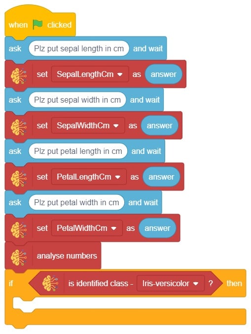
class_list = ['Iris-versicolor','Iris-virginica','Iris-setosa',] # List of all the classes
inputValue=[SepalLengthCm,SepalWidthCm,PetalLengthCm,PetalWidthCm,] # Input List
inputTensor = tf.expand_dims(inputValue, 0) # Input Tensor
predict = model.predict(inputTensor) # Making an initial prediction using the model
predict_index = np.argmax(predict[0], axis=0) # Generating index out of the prediction
predicted_class = class_list[predict_index] # Tallying the index with class list
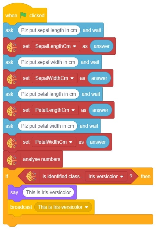
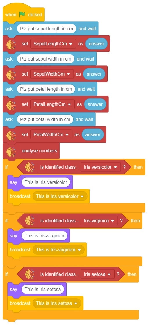
sprite.say(predicted_class)
sprite1.show()
sprite1.switchcostume(predicted_class)The example demonstrates how to count nuts and bolts from an image of a stage. Following are the key steps happening:
sprite1 = Sprite('Iris-versicolor')
sprite1.hide()SepalLengthCm= int(sprite.input("Enter Sepal Length"))
SepalWidthCm=int(sprite.input("Enter Sepal Width"))
PetalLengthCm=int(sprite.input("Enter Petal Length"))
PetalWidthCm=int(sprite.input("Enter Petal Width"))sprite1.show()sprite1.switchcostume(predicted_class)

A sign detector robotic arm is a smart robot that can recognize and understand signs or signals in its surroundings. It uses cameras and other sensors to capture visual information and computer algorithms to analyze the signs. The robot can learn different types of signs through machine learning techniques. Once a sign is identified, the robotic arm can perform specific actions based on what the sign means. These robotic arms have many uses, such as helping in healthcare, manufacturing, transportation, and assisting people with communication disabilities. They are an exciting advancement in human-robot interaction, allowing robots to understand and respond to signs, expanding their abilities and applications.

A sign detector robotic arm is a smart robot that can recognize and understand signs or signals in its surroundings. It uses cameras and other sensors to capture visual information and computer algorithms to analyze the signs. The robot can learn different types of signs through machine learning techniques. Once a sign is identified, the robotic arm can perform specific actions based on what the sign means. These robotic arms have many uses, such as helping in healthcare, manufacturing, transportation, and assisting people with communication disabilities. They are an exciting advancement in human-robot interaction, allowing robots to understand and respond to signs, expanding their abilities and applications.

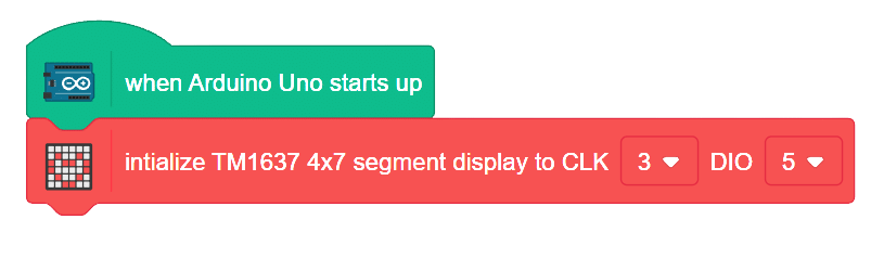
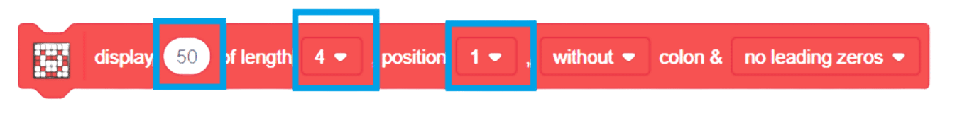
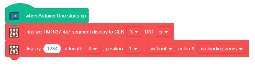
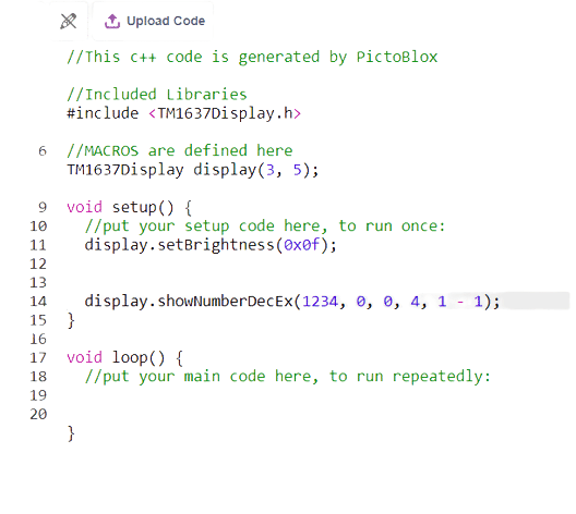
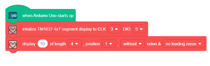
The 7 segment display is a compact arrangement of seven LEDs, creatively forming the shape of the number eight. Often, the display contains an eighth LED with a dot, functioning as a decimal point. Each LED can be controlled individually, enabling the formation of any desired number. By understanding the labeling of LEDs (A to G) and the dot LED (DP), we gain full control over this display module.
.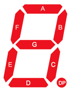
There are two types of 7-segment displays available: common cathode and common anode.
A joystick is an input device used to control the movement or actions of a computer, video game console, or other electronic device. In gaming, joysticks are often used to control the movement of characters or vehicles in a virtual environment. They provide analog input, meaning the degree of movement can vary based on how far the handle is pushed in a particular direction. In aviation and flight simulation, joysticks are commonly used to simulate the control of aircraft, providing pitch, roll, and yaw inputs. Some advanced joysticks also come with additional features such as throttle controls, programmable buttons, and force feedback to enhance the gaming or simulation experience. below is a simple animation of a joystick.
In this example, we’ll be interfacing a joystick with Quarky and try to read the values of the joystick along the x and y axis let’s begin!!
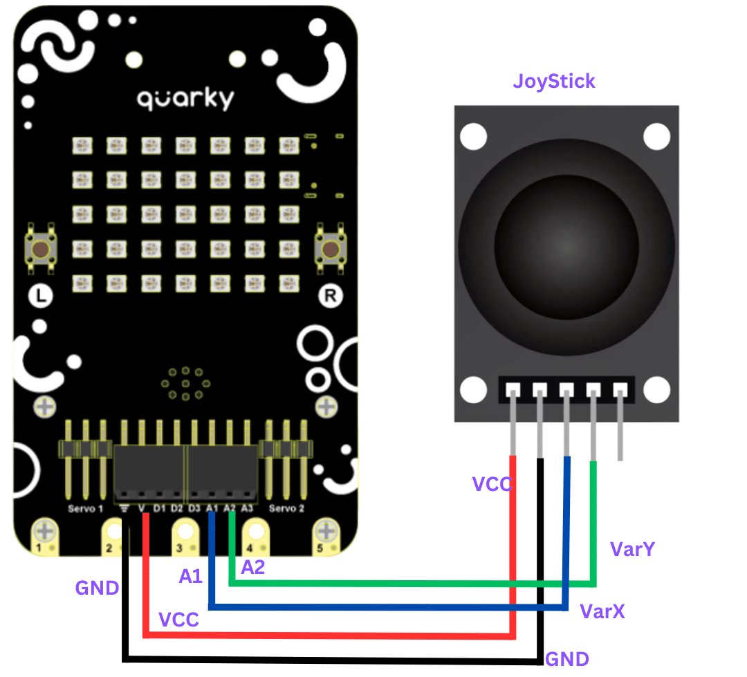
connection
JoyStick Quarky
GND GND
5V V
VarX A1
VarY A2

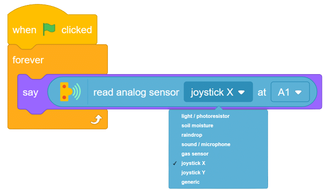
Now run the code, with this simple script, you will be able to read the value of the joystick along for X-axis in forward, backward, left, and right. with these values you will be able to set the logic on different values for fixing the direction as forward, backward, etc. do same for finding values for Y-axis.
Task for you.
Try to print the value of both the axis together

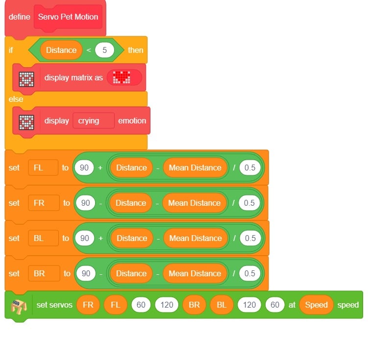
The project demonstrates how to make the Quadruped detect the hand in front of it and move according.
The logic is simple. If the distance measured from the ultrasonic sensor is less the robot will move toward the hand. Else the robot will lean backward.
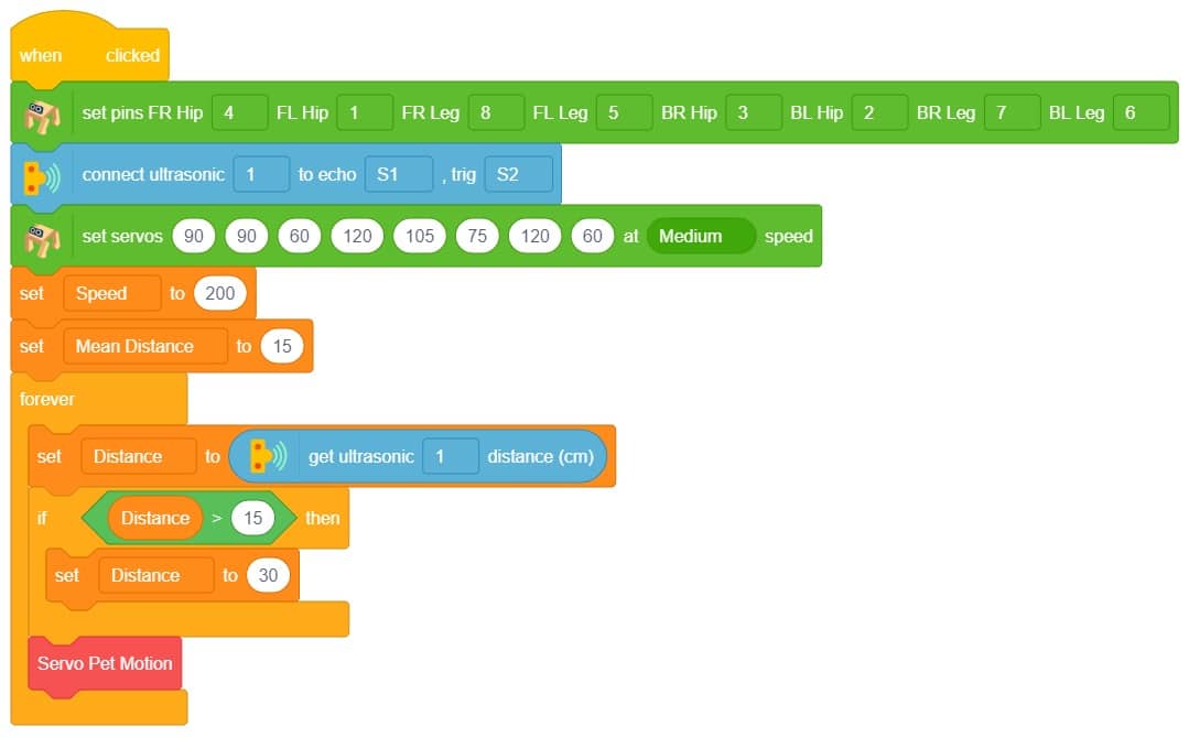
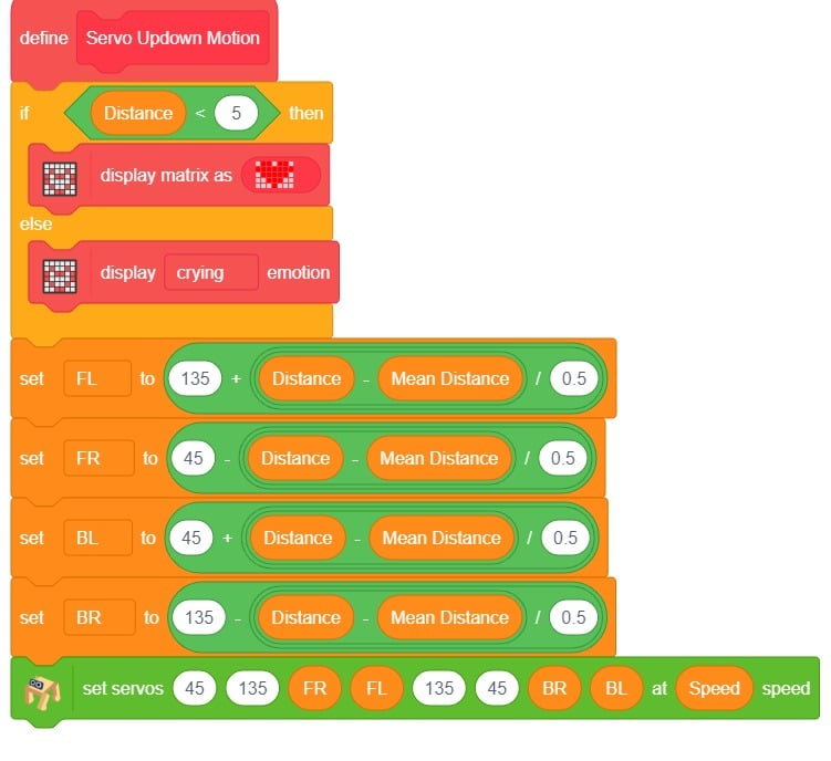
If the distance measured from the ultrasonic sensor is less the robot will face upwards towards the hand. Else the robot will look downward.


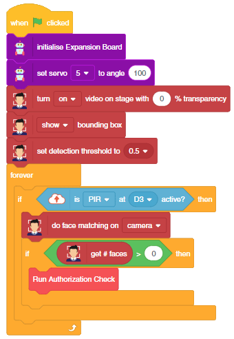
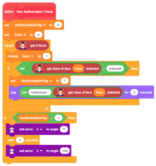
The project uses face recognition to identify authorized people and opens the door accordingly.
We are using 2 devices in this project:
We will be using Face Detection extension for making the face recognition application.
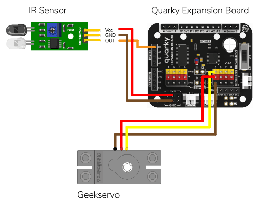
An Infrared sensor is a type of sensor that senses if something is close to it or not. The IR stands for Infrared sensor. Infrared is the light out of our visible spectrum.
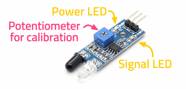
An IR sensor has a white LED (transmitter) and a photodiode (receiver). The transmitter emits IR light, and the receiver detects reflected light from objects within the sensor’s range, which can be adjusted with a potentiometer. The sensor is indicated by two LED indicators, a power LED which is always on, and a signal LED which is on when an object is detected and off when nothing is detected.
The signal LED has two states or situations:
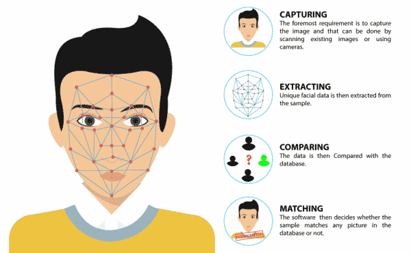
This script allows us to add a new face to the system. First, the video feed from the camera is turned on. Then, the camera is analyzed for a face. If one face has been detected, the user is asked to select a slot (1 to 10) and enter a name for the new face which is then added to the system. Finally, the video feed from the camera is turned off.
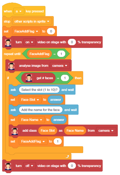
This code creates a program that can add a new face to the system, and then recognize and authenticate the user:
In this example, we will demonstrate how to control the door of the IoT House.
Connect the servo motor to the Quarky Expansion Board servo pin 5.
The door of the IoT House is controlled with a servo motor. You need to make the servo motor set to 0 angles before assembling the door. You can do it with the following code.
#Creating two objects called "quarky" and "expansion"
quarky = Quarky()

# The "expansion" object is now set to the "Expansion" class
expansion = Expansion()

# We are using the "moveservo" method from the "Expansion" class to make the servo motor 5 be set at 0-degree
expansion.moveservo(5, 0)The following script makes the door closed by default and opens it for 1 second when the space key is pressed.
import time

sprite = Sprite('Tobi') # create a sprite object called 'Tobi'
quarky = Quarky() # create a Quarky object
expansion = Expansion() # create an Expansion object

expansion.moveservo(5,100); # move the servo on pin 5 to position 100

while True: # loop forever
	if sprite.iskeypressed("space"): # if the spacebar is pressed
		expansion.moveservo(5,0); # move the servo on pin 5 to position 0
		time.sleep(1) # wait for 1 second
expansion.moveservo(5,100); # move the servo on pin 5 to position 100Press the space key to make the door open.
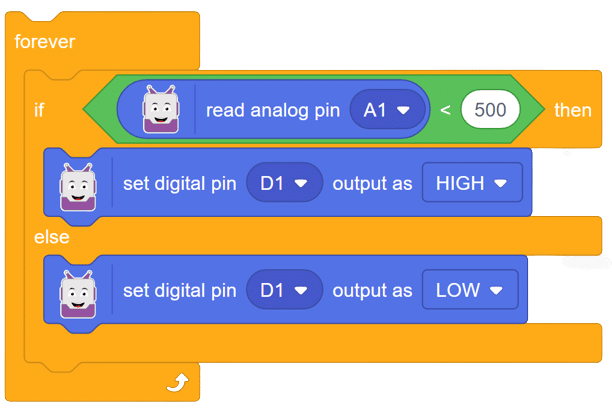
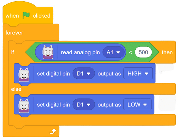
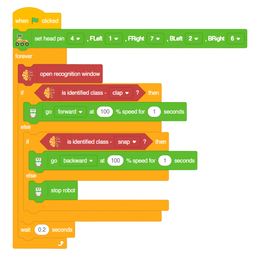
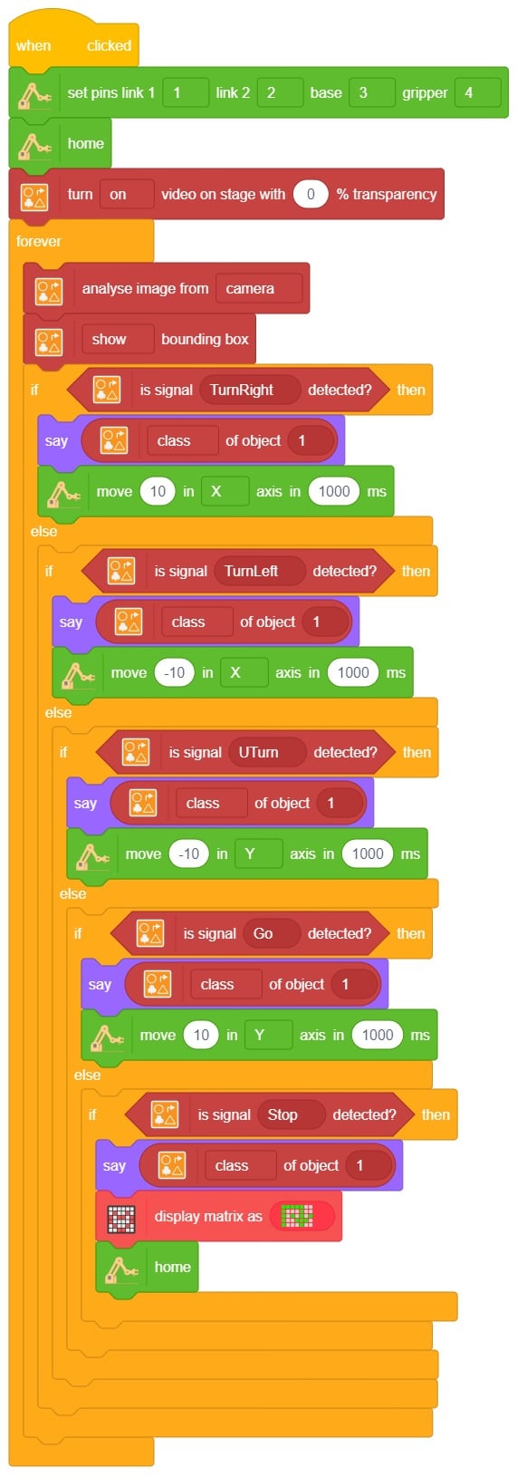
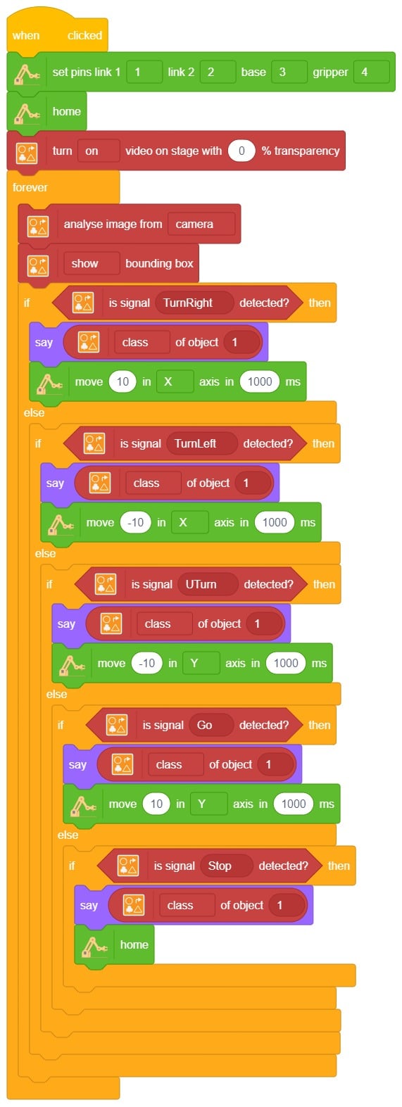
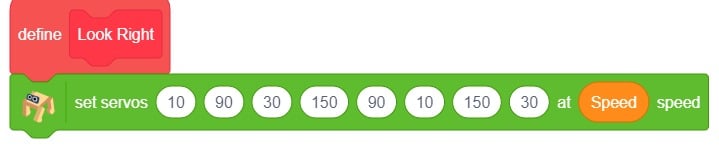
This project of obstacle avoidance is for a robot that will move around and look for obstacles. It uses an ultrasonic sensor to measure the distance. If the distance is less than 20 cm, it will stop and look in both directions to see if it can move forward. If it can, it will turn left or right. If not, it will make a U-turn. The robot will also light up an LED display to show where it is going.

This code is making a robot move around and explore its surroundings. It has an ultrasonic sensor that can measure the distance between objects.

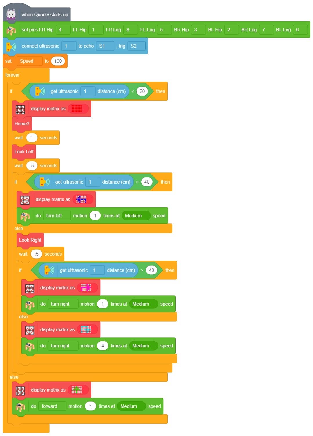
Upload the code to Quarky and test it.
This project demonstrates how to use Machine Learning Environment to make a machine–learning model that identifies hand gestures and makes the humanoid move accordingly.
We are going to use the Hand Classifier of the Machine Learning Environment. The model works by analyzing your hand position with the help of 21 data points.
Follow the steps below:
There are 2 things that you have to provide in a class:
You can perform the following operations to manipulate the data into a class.
After data is added, it’s fit to be used in model training. To do this, we have to train the model. By training the model, we extract meaningful information from the hand pose, and that in turn updates the weights. Once these weights are saved, we can use our model to predict previously unseen data.
The accuracy of the model should increase over time. The x-axis of the graph shows the epochs, and the y-axis represents the accuracy at the corresponding epoch. Remember, the higher the reading in the accuracy graph, the better the model. The range of accuracy is 0 to 1.
To test the model, simply enter the input values in the “Testing” panel and click on the “Predict” button.
The model will return the probability of the input belonging to the classes.
Click on the “Export Model” button on the top right of the Testing box, and PictoBlox will load your model into the Block Coding Environment if you have opened the ML Environment in the Block Coding.
The Humanoid will move according to the following logic:


Copyright 2025 – Agilo Research Pvt. Ltd. All rights reserved – Terms & Condition | Privacy Policy