The block reports the selected field data from the last read request from ThingSpeak.
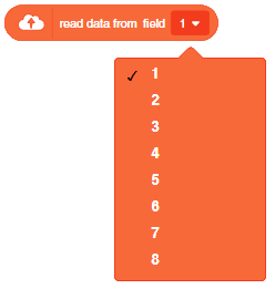
The block reports the selected field data from the last read request from ThingSpeak.

A Humanoid dance sequence is a set of programmed instructions that allows a Humanoid robot to perform a dance routine. Typically, these sequences involve a combination of movements and actions performed by the robot in a coordinated manner, to create an entertaining and engaging dance performance.
The process typically involves the following steps:
Creating a Humanoid dance sequence involves a combination of creativity, technical skill, and attention to detail, and can result in an engaging and entertaining performance that showcases the capabilities of robotic technology.
Humanoid is a class in a programming code that is used to control the movements of a humanoid robot. The code provides specific pins to control the robot’s movement, and it allows the robot to perform a series of actions such as dancing, flapping, moving forward, and other actions. We can learn how to program a humanoid robot to dance.
sprite = Sprite('Tobi')
quarky=Quarky()
import time

humanoid = Humanoid(7,2,6,3,8,1)

quarky.showemotion("surprise")
humanoid.home()
humanoid.move("forward",1000,1)
quarky.playsound("QuarkyIntro")
humanoid.action("flapping",1000,1)
time.sleep(1)
humanoid.action("dance2",1000,1)
time.sleep(1)
humanoid.action("moonwalker",1000,1)
time.sleep(1)
humanoid.action("dance1",1000,1)
time.sleep(1)
humanoid.action("forward",1000,1)
time.sleep(1)
Humanoid.action("tiptoeswing",1000,1)
time.sleep(1)
Humanoid.action("swing",1000,1)
time.sleep(1)
Humanoid.action("flapping",1000,1)
time.sleep(1)
Humanoid.action("updown",1000,1)
Humanoid.home()

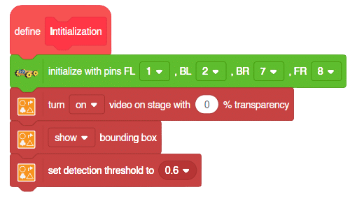
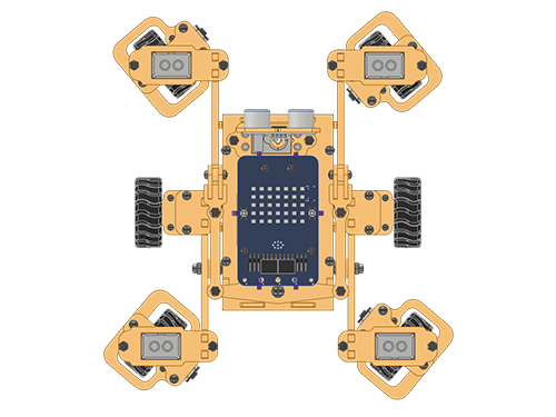
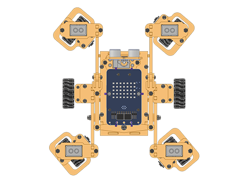
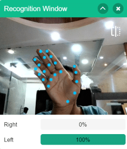
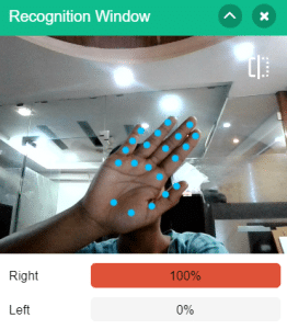
A sign detector Mecanum robot is a robot that can recognize and interpret certain signs or signals, such as hand gestures or verbal commands, given by a human. The robot uses sensors, cameras, and machine learning algorithms to detect and understand the sign, and then performs a corresponding action based on the signal detected.
These robots are often used in manufacturing, healthcare, and customer service industries to assist with tasks that require human-like interaction and decision making.
sprite = Sprite('Tobi')
quarky = Quarky()
import time
meca=Mecanum(1,2,7,8)
recocards = RecognitionCards()
recocards.video("on flipped")
recocards.enablebox()
recocards.setthreshold(0.6)
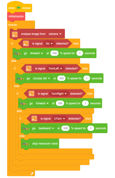
while True:
recocards.analysecamera()
sign = recocards.classname()
sprite.say(sign + ' detected')
if recocards.count() > 1:
if 'Go' in sign:
meca.runtimedrobot("forward",100,2)
if 'Turn Left' in sign:
meca.runtimedrobot("lateral left",100,2)
if 'Turn Right' in sign:
meca.runtimedrobot("lateral right",100,2)
if 'U Turn' in sign:
meca.runtimedrobot("backward",100,2)Forward Motion:
Right-Left Motions:
A sign detector Mecanum robot is a robot that can recognize and interpret certain signs or signals, such as hand gestures or verbal commands, given by a human. The robot uses sensors, cameras, and machine learning algorithms to detect and understand the sign, and then performs a corresponding action based on the signal detected.
These robots are often used in manufacturing, healthcare, and customer service industries to assist with tasks that require human-like interaction and decision making.
Initialization:
Main Code
Forward Motion:
Right-Left Motions:

In this project, we will explain how to run predefined actions for Quadruped. By the end of the tutorial, learners will have gained knowledge and practical experience in programming a quadruped robot and controlling its movements using PictoBlox.
sprite = Sprite('Tobi')
quarky = Quarky()
import time

quad=Quadruped(4,1,8,5,3,2,76)

while True:
  quad.home()
  time.sleep(0.2)
  quad.action("dance1",1000,1)
  time.sleep(0.5/2)
  quad.action("updown1",1000,2)
  time.sleep(0.2)
  quad.action("front back",1000,1)
  time.sleep(0.2)
  quad.action("march in place",1000,1)
  time.sleep(0.2)
  quad.action("left hand wave",1000,1)
  time.sleep(0.2)
  quad.action("right hand wave",1000,1)
  time.sleep(0.2)
  quad.action("bodyshake4",1000,2)
  time.sleep(0.2)
  quad.action("dance5",1000,2)
  time.sleep(0.2)
  quad.action("creepy",1000,2)
  quad.home()

Are you looking for a way to make a robotic arm that can be controlled wirelessly? If so, you’ve come to the right place! This tutorial will teach you how to control a Quarky robotic arm using the Bluetooth communication extensions of Quarky and PictoBlox. With this technique, you’ll be able to provide precise control over its movement and actions from a remote location.
The robotic arm can be used for various tasks, such as picking up objects or manipulating tools. It can also be used for applications like manufacturing, medical, research, and exploration. This type of robotic arm will increase the productivity and safety of operations that would otherwise be too hazardous or inaccessible for humans.
Let’s get started learning how to create a wirelessly controlled robotic arm.
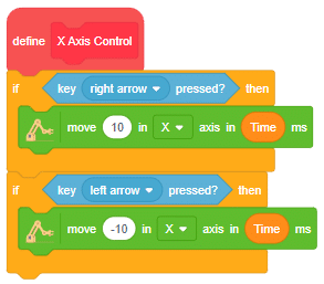
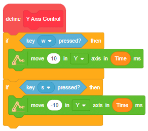
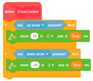
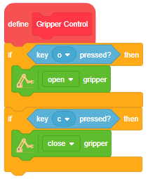
In this project, we are making Quarky Robotic Arm to be controlled wirelessly using keyboard inputs. Following are the controls we will program:
Following is the code to implement the project:
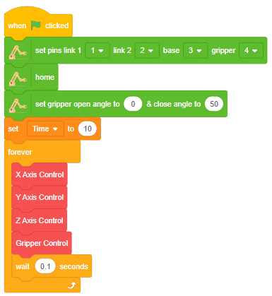
Run the program to test the code.
You can explore doing pick and place using the robotic arm.

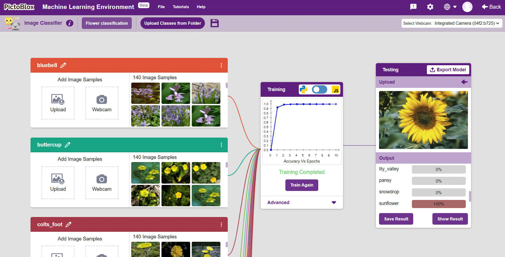
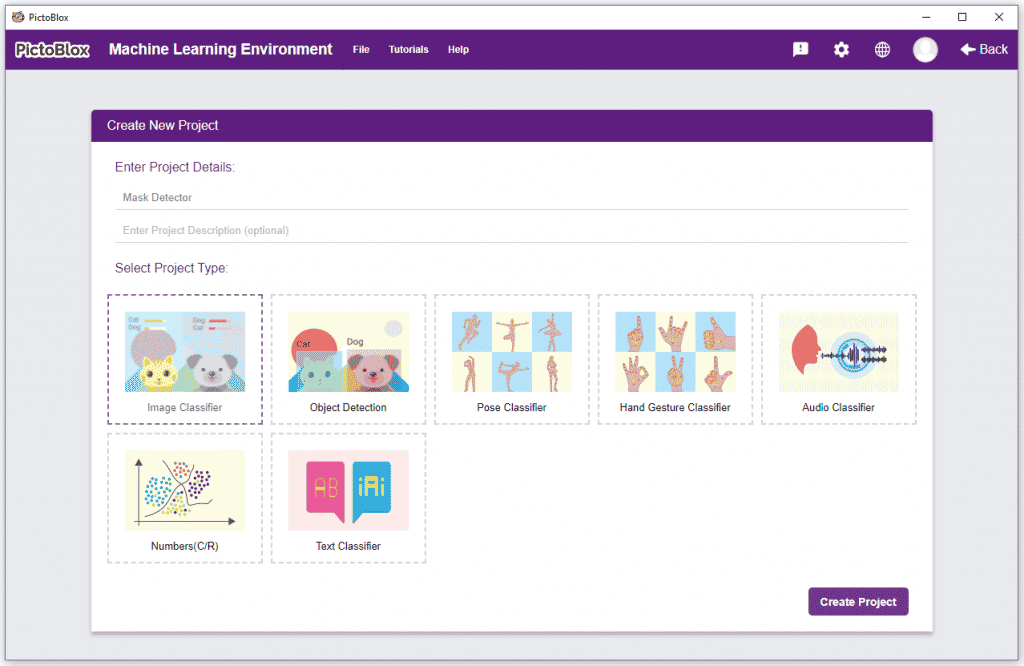
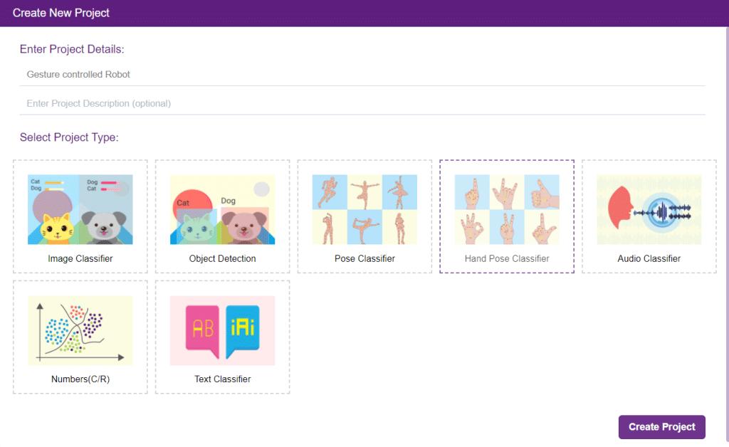
In this example project we are going to create a Machine Learning Model which can identify the type of flower from the camera feed or images.
Image Classifier is an extension of the ML environment that allows users to classify images into different classes. This feature is available only in the desktop version of PictoBlox for Windows, macOS, or Linux. As part of the Image Classifier workflow, users can add classes, upload data, train the model, test the model, and export the model to the Block Coding Environment.
Let’s create the ML model.

Alert: The Machine Learning Environment for model creation is available in the only desktop version of PictoBlox for Windows, macOS, or Linux. It is not available in Web, Android, and iOS versions.
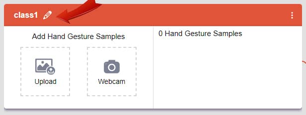
Follow the steps below:
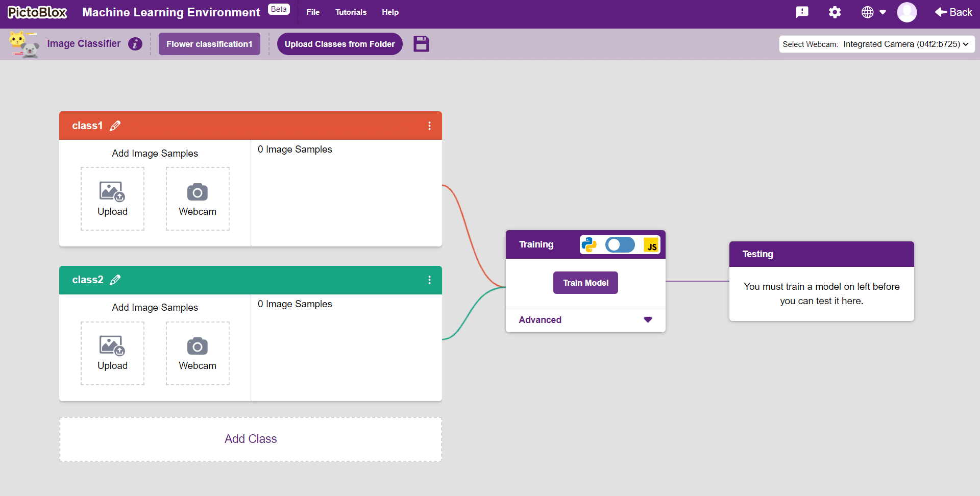
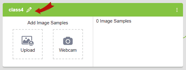
Class is the category in which the Machine Learning model classifies the images. Similar images are put in one class.
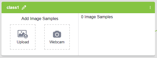
There are 2 things that you have to provide in a class:


You can perform the following operations to manipulate the data into a class.
After data is added, it’s fit to be used in model training. In order to do this, we have to train the model. By training the model, we extract meaningful information from the images, and that in turn updates the weights. Once these weights are saved, we can use our model to make predictions on data previously unseen.
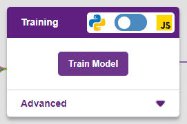
However, before training the model, there are a few hyperparameters that you should be aware of. Click on the “Advanced” tab to view them.
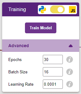
It’s a good idea to train a numeric classification model for a high number of epochs. The model can be trained in both JavaScript and Python. In order to choose between the two, click on the switch on top of the Training panel.
Note: These hyperparameters can affect the accuracy of your model to a great extent. Experiment with them to find what works best for your data.
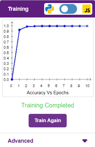
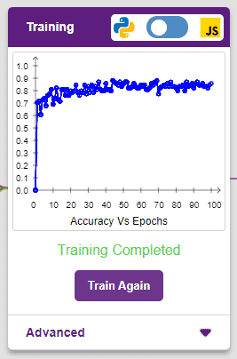
The accuracy of the model should increase over time. The x-axis of the graph shows the epochs, and the y-axis represents the accuracy at the corresponding epoch. Remember, the higher the reading in the accuracy graph, the better the model. The x-axis of the graph shows the epochs, and the y-axis represents the corresponding accuracy. The range of the accuracy is 0 to 1.
Other evaluating parameter we can see by clicking on Train Report
Here we can see confusion matrix and training accuracy of individual classes after training.
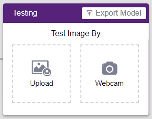
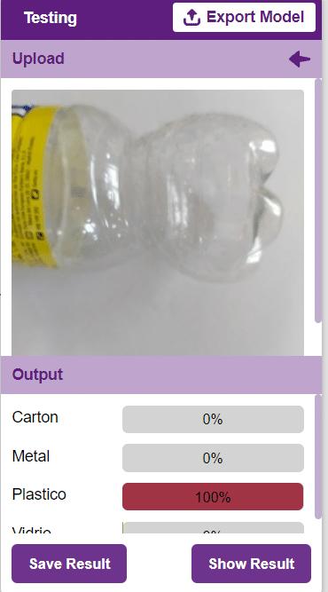
To test the model, simply enter the input values in the “Testing” panel and click on the “Predict” button.
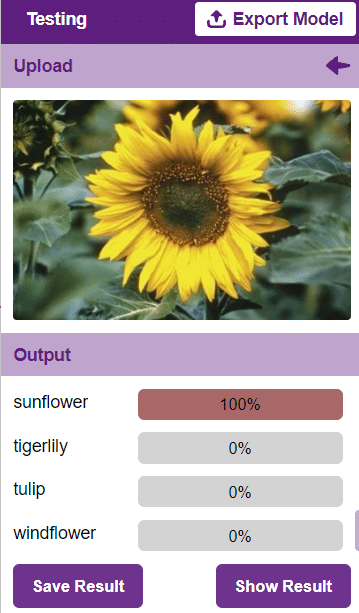
The model will return the probability of the input belonging to the classes.
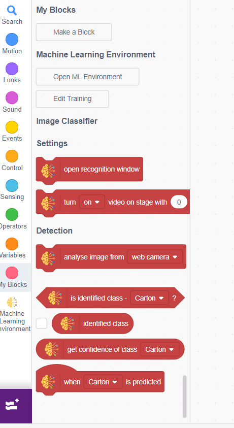
Click on the “Export Model” button on the top right of the Testing box, and PictoBlox will load your model into the Block Coding Environment if you have opened the ML Environment in the Block Coding.
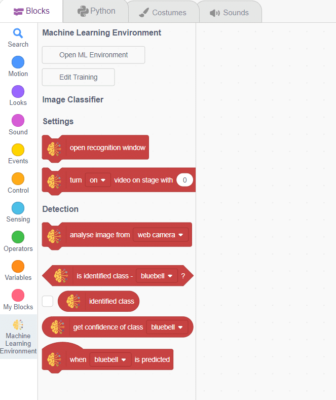
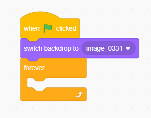
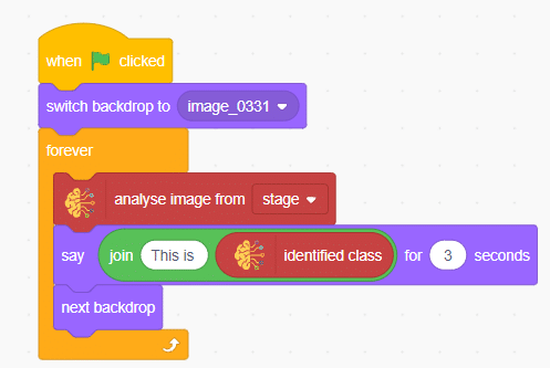
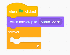
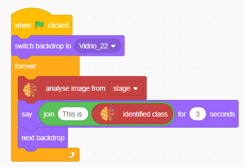
The idea is simple, we’ll add image samples in the “Backdrops” column. We’ll keep cycling through the backdrops and keep classifying the image on the stage.
Automatic Robotic AMR stands for Automatic Mobile Robots for Autonomous Material Handling. It refers to a class of robots that are designed to autonomously transport and handle materials in various environments, such as warehouses, factories, hospitals, and distribution centers.
sprite = Sprite('Tobi')

import time

roboticArm = RoboticArm(1,2,3,4,)

roboticArm.setgripperangle(90,145)
roboticArm.sethome()
while True:
	roboticArm.controlgripper("open")
	roboticArm.movexyzonebyone(0,200,15,1000)
	roboticArm.gotoinoneaxis(180,"Y",1000)
	roboticArm.controlgripper("close")
	roboticArm.gotoinoneaxis(150,"X",1000)
	roboticArm.controlgripper("open")
	roboticArm.sethome()
	roboticArm.controlgripper("close")
	time.sleep(1)
	roboticArm.controlgripper("open")
	roboticArm.movexyzonebyone(-60,160,10,1000)
	roboticArm.gotoinoneaxis(200,"Y",1000)
	roboticArm.gotoinoneaxis(15,"Z",1000)
	roboticArm.gripperaction("close")
	roboticArm.gotoinoneaxis(150,"X",1000)
	roboticArm.gripperaction("open")
	roboticArm.sethome()
	roboticArm.gripperaction("close")
	time.sleep(0.2)

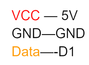
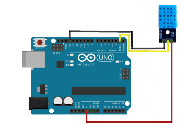
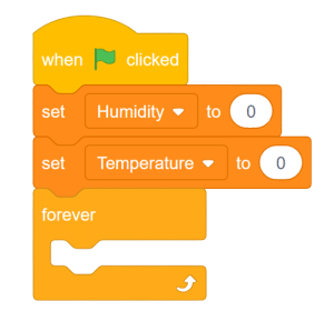
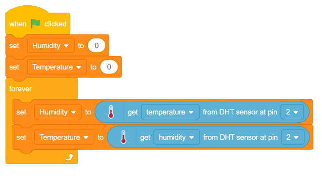
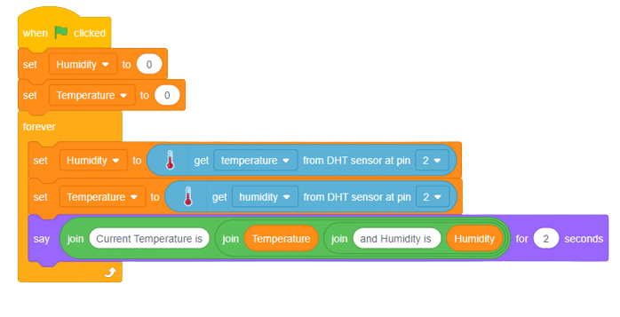
DHT11 is a low-cost digital sensor for sensing temperature and humidity. This sensor can be easily interfaced with any micro-controller such as Arduino, Raspberry Pi etc. to measure humidity and temperature instantaneously. It comes with a dedicated NTC to measure temperature and an 8-bit microcontroller to output the values of temperature and humidity as serial data. The DHT11 sensor has three pins- VCC, GND and Data Pin. A pull-up resistor of 5k to 10k ohms is provided for communication between sensor and microcontroller.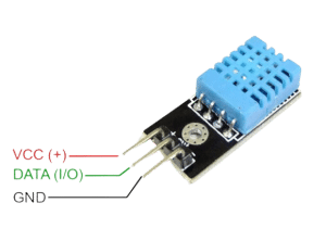
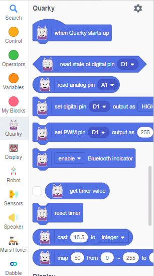
Quarky is a powerful microcontroller that allows for custom programming of projects, ranging from basic to advanced levels. With various built-in features such as sensors, actuators, and a speaker, Quarky becomes the perfect companion for those venturing into the world of robotics and AI. Its compact size and plug-and-play functionality make it an ideal choice for students eager to learn and experiment with robotics.
![]()

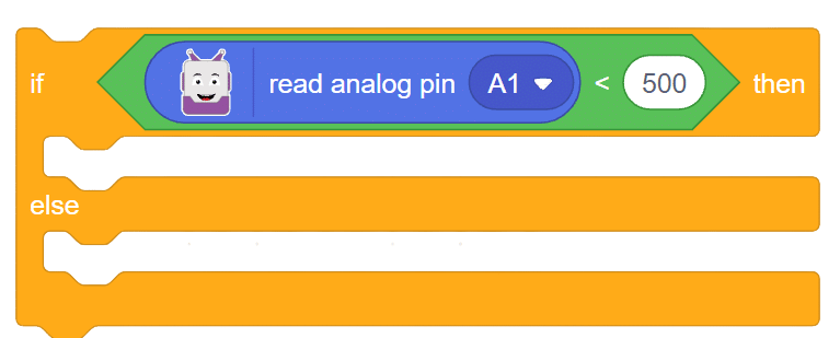
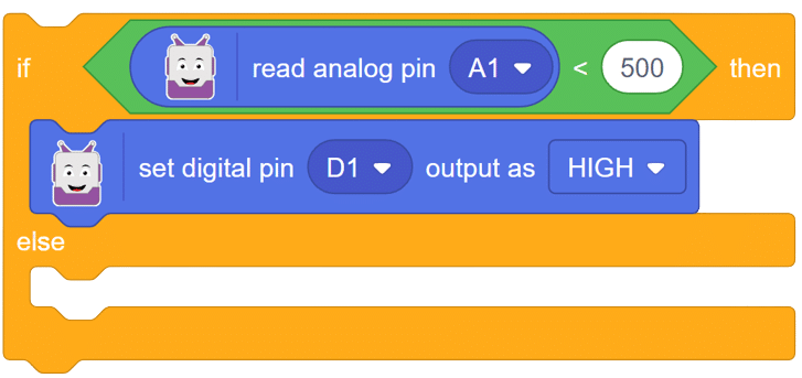
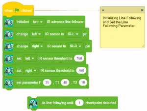
Follow these steps to implement the code using Pictoblox for Quarky to control the LED based on the IR sensor’s readings:
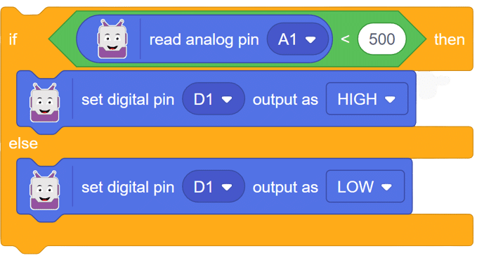
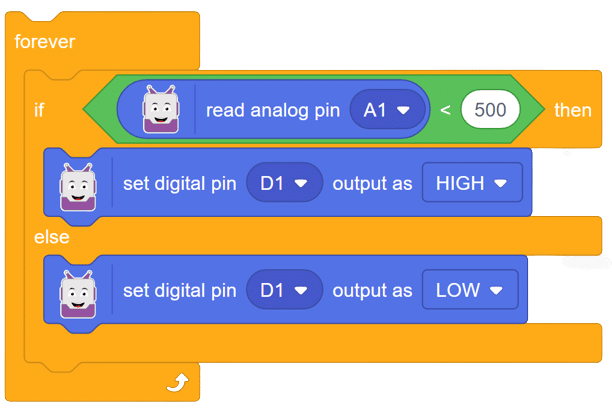
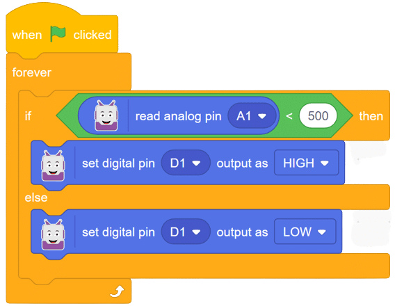
In this comprehensive introduction, you have learned about Quarky, the versatile microcontroller, and its potential in robotics and AI projects. Explore its various features, sensors, and plug-and-play functionality. Follow our step-by-step guide to set up the circuit with the IR sensor and LED, and program Quarky using Pictoblox’s block coding. Witness the successful implementation through the final script and output, experiencing the magic of Quarky in action!

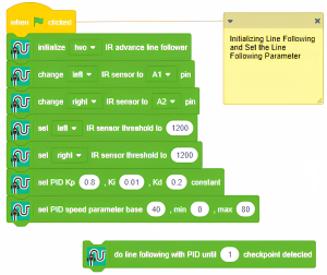
Steps :
1. Set IR threshold for stopping the robot at the crossing lines
2. Use a block to get IR value for reading IR value
3. The below example uses a pid line following blocks
4. When you click doline following robot start line following and stop at the check-point(when both IRs are at the Black line)
Script
Output
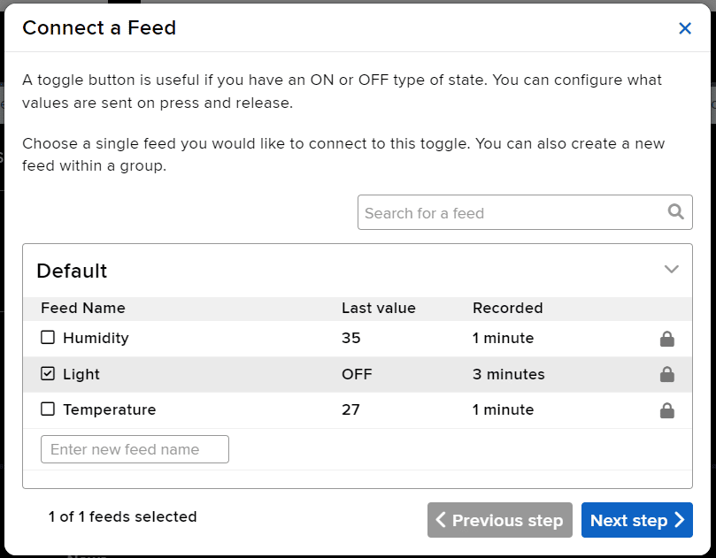
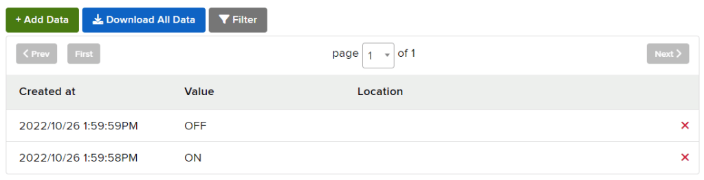
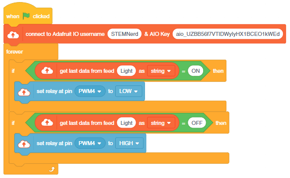
In this example, we will retrieve the color information from the cloud and make the Quarky lights ON and OFF with the selected color on the cloud.
The following script reads the Light feed value and makes the Quarky light up accordingly.

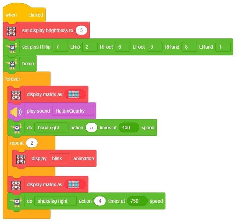
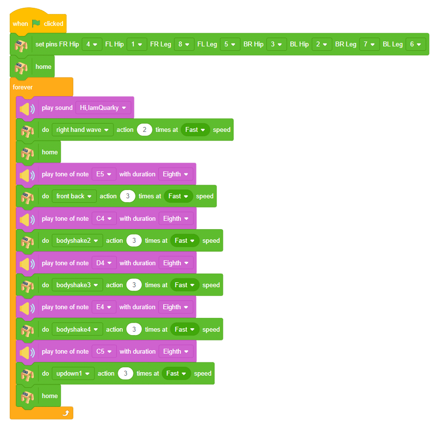
The example demonstrates how to create a dance sequence with Quadruped with Music.

When Quarky‘s left pushbutton is pressed, it will wait for 1 second and play a sound. After that, Quadruped will wave its right hand and move back to the “home“ position. Then Quarky will play different tones and Quadruped will do different actions. Finally, Quadruped will move back to the “home“ position.
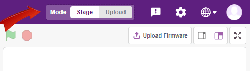
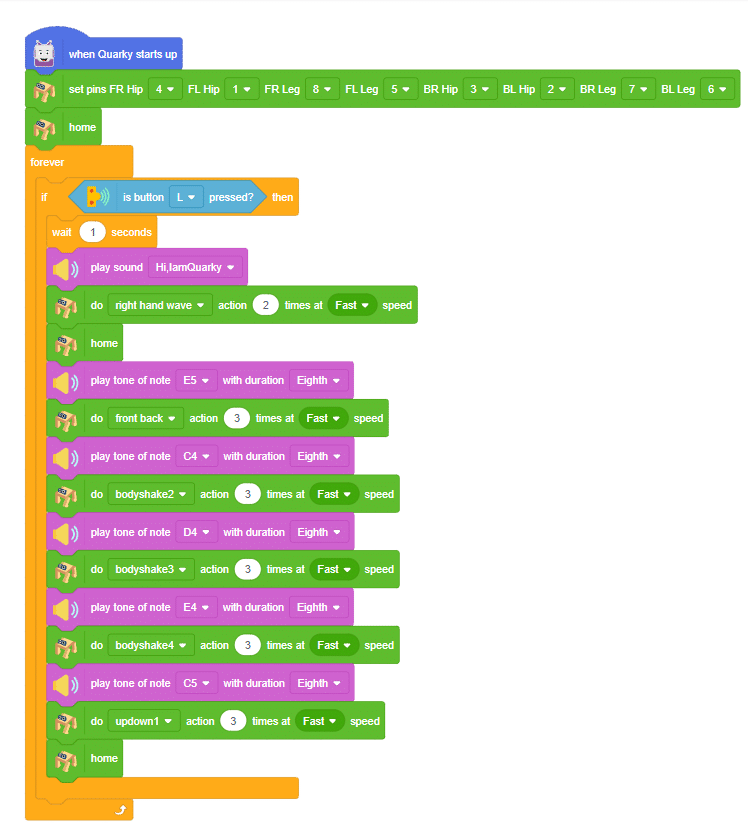
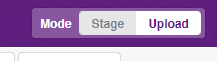
You can also make the Quadruped dance work independent of PictoBlox using the Upload Mode. For that switch to upload mode and replace the when green flag clicked block with when Quarky starts up the block.
We will make the Quadruped start the dance sequence when the Left key is pressed.

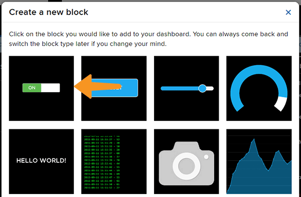
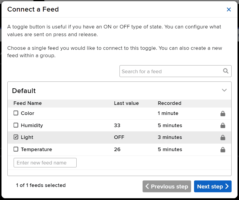
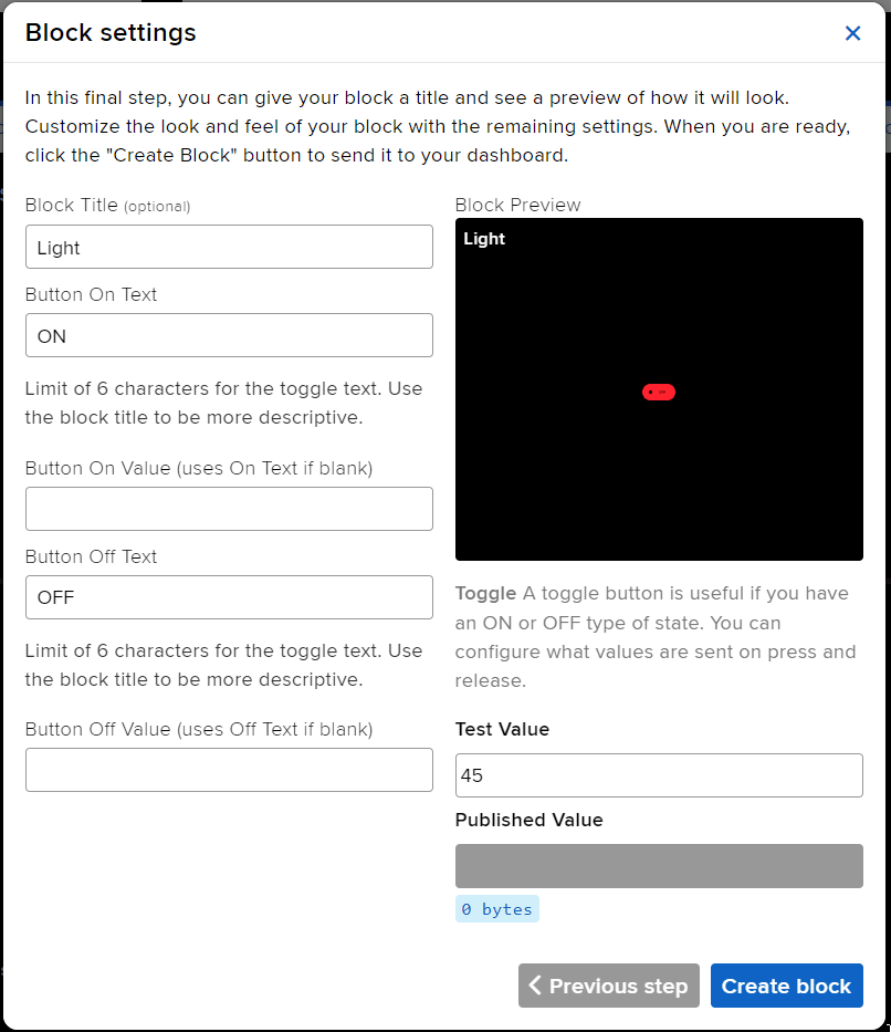
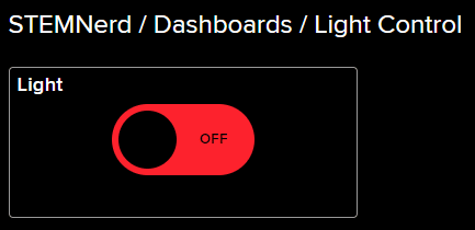
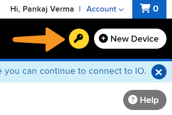
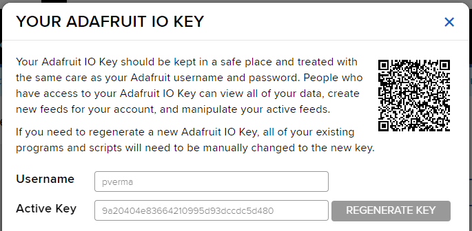
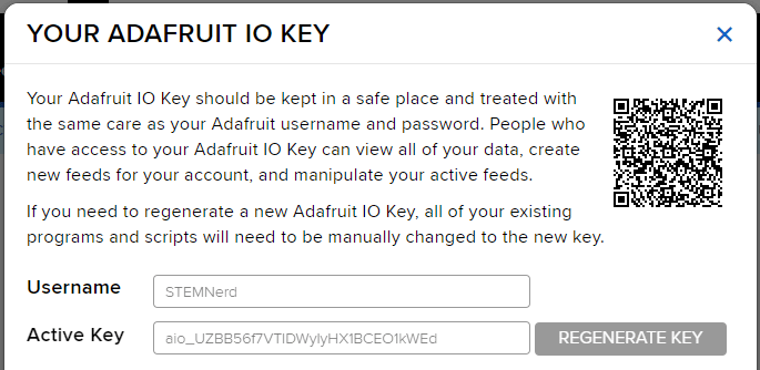
In this example, we are going to understand how to make a feed on Adafruit IO. Later we will write the Python code that will retrieve the information from the cloud and make the Quarky lights ON and OFF.
You can find the information about your account once you log in from here:
This Python code creates two instances, one of the Quarky class and one of the AdaIO class. It sets the brightness of the Quarky instance to 10 and connects to Adafruit IO using the specified username and key. It then creates a loop that checks to see if the value of the “Light“ feed from Adafruit IO is “ON“. If the data is “ON” then the white light is turned on on the display, otherwise, the display is cleared.
# Create a new instance of the Quarky class and call it quarky
quarky = Quarky()

# Create a new instance of the AdaIO class and call it adaio
adaio = AdaIO()

# Set the brightness of Quarky to 10
quarky.setbrightness(10)

# Connect to Adafruit IO using the specified username and key
adaio.connecttoadafruitio("STEMNerd", "aio_UZBB56f7VTIDWyIyHX1BCEO1kWEd")

# Create an loop
while True:

  # Check to see if the value of the "Light" feed from Adafruit IO is "ON"
  if (adaio.getdata("Light") == "ON"):
    # If the data is "ON" draw the specified pattern
    quarky.drawpattern("aaaaaaaaaaaaaaaaaaaaaaaaaaaaaaaaaaa")

  # Otherwise, clear the display
  else:
    quarky.cleardisplay()
You can also make the script work independently of PictoBlox using the Upload Mode. For that switch to upload mode.
# This code connects to a wifi network and an adafruit IO account.
# It also uses the module "quarky" to set the brightness and draw a pattern.
# The code will check if the wifi is connected and if the value of "Light" in the adafruit IO account is "ON",
# it will draw a pattern on the display. If not, it will clear the display.
# If the wifi is not connected, it will set LED 1 to red.

from quarky import *

# imported module
import iot

# Connect to a wifi network
wifi = iot.wifi()
wifi.connecttowifi("IoT", "12345678")

# Connect to an adafruit IO account
adaio = iot.AdaIO()
adaio.connecttoadafruitio("STEMNerd", "aio_UZBB56f7VTIDWyIyHX1BCEO1kWEd")

# Set the brightness
quarky.setbrightness(10)

while True:
  # Check if the wifi is connected
  if wifi.iswificonnected():
    # Check if the value of "Light" in the adafruit IO account is "ON"
    if (adaio.getdata("Light") == "ON"):
      # Draw a while LED pattern on the display
      quarky.drawpattern("aaaaaaaaaaaaaaaaaaaaaaaaaaaaaaaaaaa")
    else:
      # Clear the display
      quarky.cleardisplay()
  else:
    # Set LED 1 to red
    quarky.setled(1, 1, [255, 0, 0], 100)
Troubleshooting:
In the last project, we looked at the Mars Rover control for turning left and right.
Instead of rotating the Mars Rover at a place to turn left or right, you can alternatives make the Mars Rover move in a circle.
This can be executed with the set () to () block. You have 2 other options Left and Right.

The following code sets the servo motor position to the left, straight, and right when the a, s, and d keys are pressed. Then to move the Mars Rover, the code checks if the up and down key is pressed.
Make the code and play with the Mars Rover.
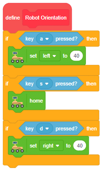
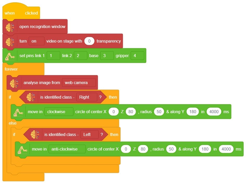
Circular Right-Left Motion


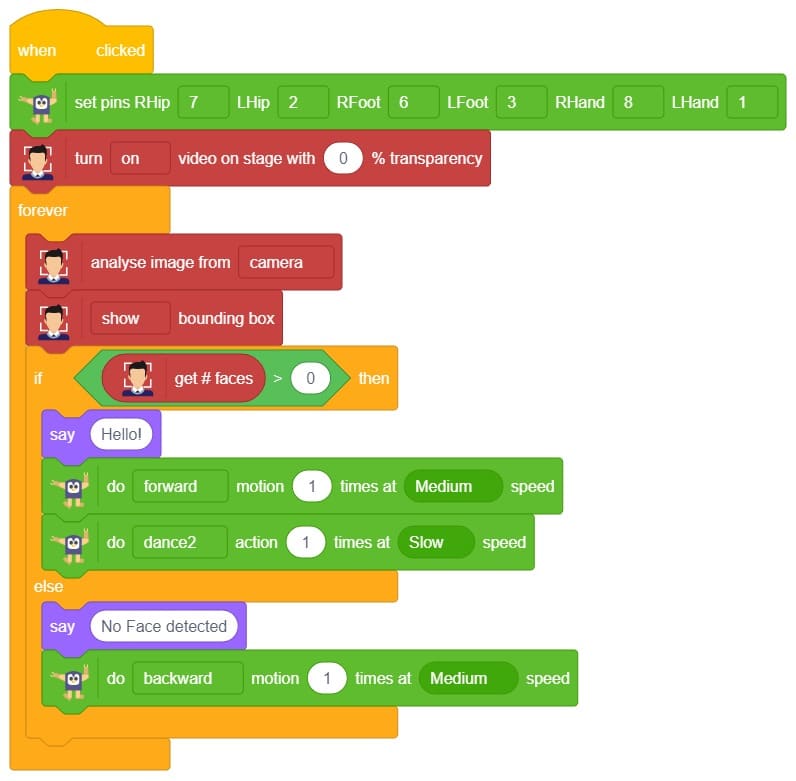
AI-based face expression detection refers to the use of artificial intelligence algorithms and computer vision techniques to analyze images or videos of human faces and recognize the emotions or expressions being displayed. The technology can detect and analyze subtle changes in facial features, such as eye movement, mouth shape, and eyebrow position, to determine whether a person is happy, sad, angry, surprised, or expressing other emotions.
Discover the various fields that utilize this technology, including psychology, marketing, and human-computer interaction. Additionally, read about the logic and code behind face detection with a camera feed, including the initialization of parameters, face detection library, loop execution, and if-else conditions. Explore how the technology continuously analyzes emotions, and how the Humanoid responds with different facial expressions and movements.
sprite = Sprite('Tobi')
fd = FaceDetection()
quarky = Quarky()
import time

humanoid = Humanoid(7, 2, 6, 3, 8, 1)

# Turn the video ON with 0% transparency
fd.video("ON", 0)
fd.enablebox()

# Run this script forever
while 1:
  fd.analysecamera()          # Analyse image from camera
  sprite.say(fd.expression()) # Say the face expressions

  if fd.isexpression(1, "happy"): # if face expression is happy
    quarky.showemotion("happy")   # show happy emotion on Quarky
    humanoid.action("dance2", 1000, 1)

  if fd.isexpression(1, 'sad'):
    quarky.showemotion("crying")
    humanoid.action("updown", 1000, 1)

  if fd.isexpression(1, 'surprise'):
    quarky.showemotion('surprise')
    humanoid.action("moonwalker", 1000, 1)

  if fd.isexpression(1, 'angry'):
    quarky.showemotion('angry')
    humanoid.action("flapping2", 1000, 1)
  else:
    humanoid.home()

# Comment the above script, uncomment the below script and
# run this script to clear the stage and quarky display

fd.disablebox()
fd.video("off")
quarky.cleardisplay()The example demonstrates how to use face detection with a camera feed. Following are the key steps happening:

As we start learning artificial intelligence, let’s make it more engaging by incorporating a fun activity. One of the most popular topics in AI is face detection, and we can make it even more exciting by learning it with the help of Humanoid robots. Are you interested in learning it together?

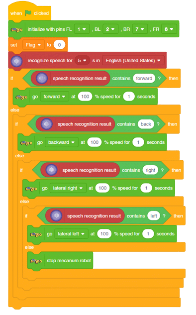
Learn how to code logic for speech recognized control of Mecanum with this example block code. You will be able to direct your own Mecanum easily by just speaking commands.
A speech recognized controlled Mecanum robot is a robot that can recognize and interpret our speech, verbal commands, given by a human. The code uses the speech recognition model that will be able to record and analyze your speech given and react accordingly on the Mecanum.
Speech recognition robots can be used in manufacturing and other industrial settings to control machinery, perform quality control checks, and monitor equipment.
They are also used to help patients with disabilities to communicate with their caregivers, or to provide medication reminders and other health-related information.
sprite=Sprite('Tobi')
import time
meca=Mecanum(1,2,7,8)
quarky = Quarky()
sr = SpeechRecognition()
ts = TexttoSpeech()
sr.analysespeech(4, "en-US")
command = sr.speechresult()
command = command.lower()
if 'forward' in command:
  meca.runtimedrobot("forward",100,2)
elif 'back' in command:
  meca.runtimedrobot("backward",100,2)
elif 'right' in command:
  meca.runtimedrobot("lateral right",100,2)
elif 'left' in command:
  meca.runtimedrobot("lateral left",100,2)

time.sleep(10)
sprite.stopallsounds()
A speech recognized controlled Mecanum robot is a robot that can recognize and interpret our speech, verbal commands, given by a human. The code uses the speech recognition model that will be able to record and analyze your speech given and react accordingly on the Mecanum.
Speech recognition robots can be used in manufacturing and other industrial settings to control machinery, perform quality control checks, and monitor equipment.
They are also used to help patients with disabilities to communicate with their caregivers, or to provide medication reminders and other health-related information.
The example demonstrates how to create a dance sequence with Quadruped with Music.
sprite = Sprite('Tobi')
quarky = Quarky()
import time

quad=Quadruped(4,1,8,5,3,2,7,6)


quad.home()
while True
	quarky.playsound("QuarkyIntro")
	quad.action("right hand wave",700,2)
	quad.home()
	quarky.playtone("E5",8)
	quad.action("front back",700,3)
	quarky.playtone("C4",8)
	quad.action("bodyshake2",700,3)
	quarky.playtone("D4",8)
	quad.action("bodyshake3",700,3)
	quarky.playtone("E4",8)
	quad.action("bodyshake4",700,3)
	quarky.playtone("C5",8)
	quad.action("updown1",700,3)
	quad.home()
You can also make the Quadruped dance work independent of PictoBlox using the Upload Mode. For that switch to upload mode. 

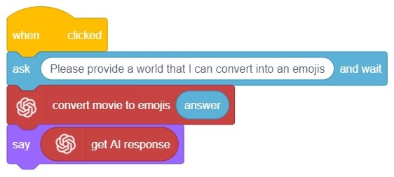
Are you looking to add some fun and expressiveness to your conversations? Look no further! I’m here to help you convert any word or phrase into a colorful array of emojis. Whether you want to spice up your messages, or social media posts, or simply bring a smile to someone’s face, I’ve got you covered.
Just type in the word or phrase you want to transform, and I’ll generate a delightful sequence of emojis that capture the essence of your text. Emojis are a universal language that transcends words from happy faces to animals, objects, and everything in between.
So, let’s get started and infuse your text with a touch of emoji magic! 🎉🔥
This code allows the user to interact with the sprite and provide emojis, which are then transformed into a response using the ChatGPT model. The sprite then speaks the generated response using the provided emojis.
sprite = Sprite('Tobi')
gpt = ChatGPT()

sprite.input("Please let me know which emojis you'd like me to use by typing them here.")
answer= str(sprite.answer())

gpt.movieToemoji(answer)
result=gpt.chatGPTresult()

sprite.say(result,5)

Are you looking to add some fun and expressiveness to your conversations? Look no further! I’m here to help you convert any word or phrase into a colorful array of emojis. Whether you want to spice up your messages, or social media posts, or simply bring a smile to someone’s face, I’ve got you covered.
Just type in the word or phrase you want to transform, and I’ll generate a delightful sequence of emojis that capture the essence of your text. Emojis are a universal language that transcends words from happy faces to animals, objects, and everything in between.
So, let’s get started and infuse your text with a touch of emoji magic! 🎉🔥
This code allows the user to interact with the sprite and provide emojis, which are then transformed into a response using the ChatGPT model. The sprite then speaks the generated response using the provided emojis.

A gesture-controlled robotic arm is a robotic arm that can be controlled using hand or body movements instead of traditional buttons or joysticks. It uses sensors and algorithms to interpret the gestures made by a user and translates them into commands for the robotic arm.
The user wears or holds a device with sensors, such as a glove or wristband, that captures their hand movements or body gestures. These movements are processed by a computer or microcontroller, which analyzes them and recognizes specific gestures using algorithms and machine learning techniques.
Once the gestures are recognized, the system generates commands for the robotic arm to move accordingly. The arm can have multiple joints and degrees of freedom to perform complex movements. The user’s gestures are mimicked by the robotic arm, allowing them to control its actions.
Gesture-controlled robotic arms are used in various fields, including manufacturing, healthcare, and virtual reality. They provide a more intuitive and natural way of controlling robotic systems, eliminating the need for complex input devices and extensive training.
Follow the steps below:
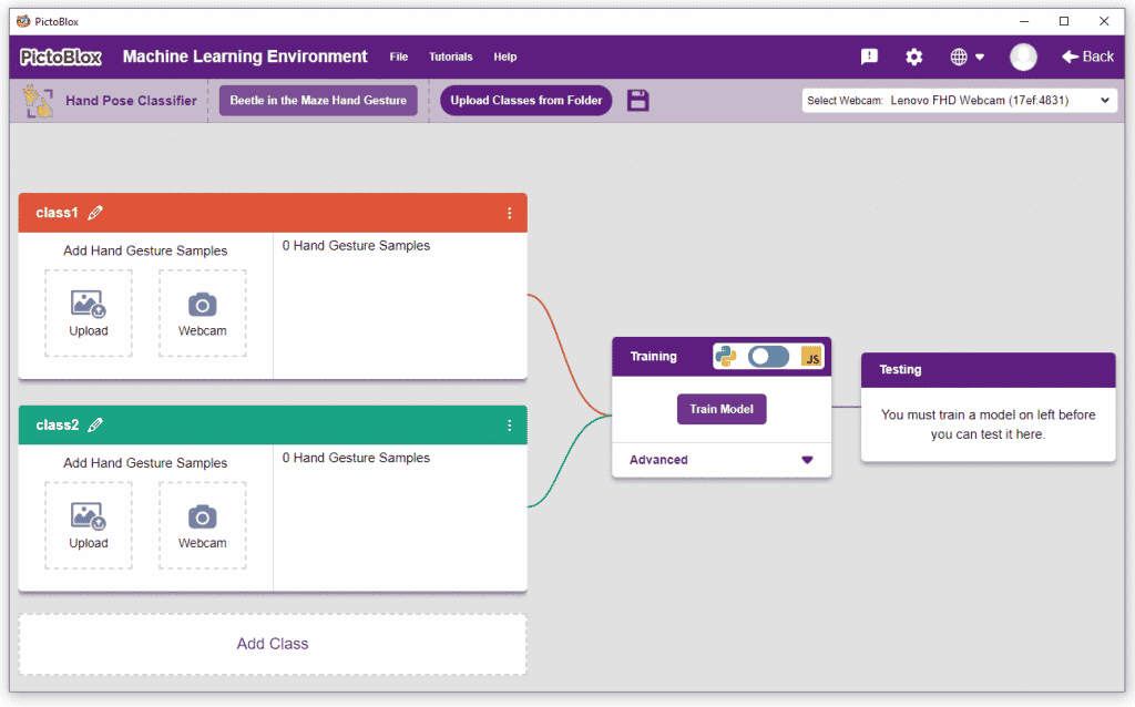
There are 2 things that you have to provide in a class:
You can perform the following operations to manipulate the data into a class.
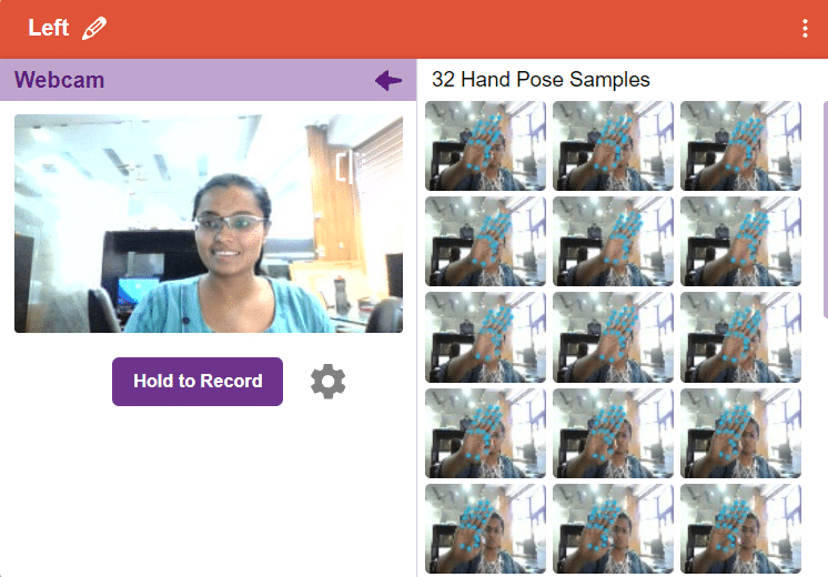
After data is added, it’s fit to be used in model training. To do this, we have to train the model. By training the model, we extract meaningful information from the hand pose, and that in turn updates the weights. Once these weights are saved, we can use our model to predict previously unseen data.
The accuracy of the model should increase over time. The x-axis of the graph shows the epochs, and the y-axis represents the accuracy at the corresponding epoch. Remember, the higher the reading in the accuracy graph, the better the model. The range of accuracy is 0 to 1.
To test the model, simply enter the input values in the “Testing” panel and click on the “Predict” button.
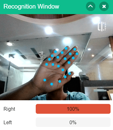
The model will return the probability of the input belonging to the classes.
Click on the “Export Model” button on the top right of the Testing box, and PictoBlox will load your model into the Block Coding Environment if you have opened the ML Environment in the Block Coding.
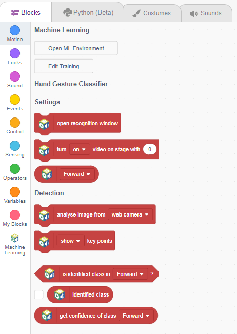
The robotic arm will move according to the following logic:


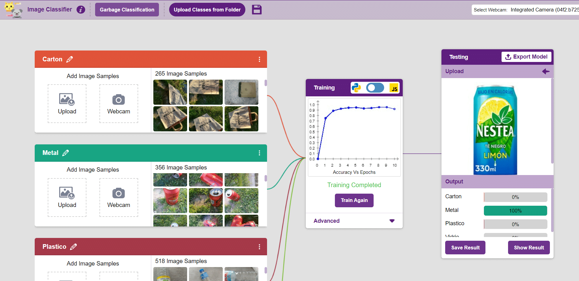
In this example project we are going to create a Machine Learning Model which can identify the type of waste from the camera feed or images.
Image Classifier is an extension of the ML environment that allows users to classify images into different classes. This feature is available only in the desktop version of PictoBlox for Windows, macOS, or Linux. As part of the Image Classifier workflow, users can add classes, upload data, train the model, test the model, and export the model to the Block Coding Environment.
Let’s create the ML model.
Alert: The Machine Learning Environment for model creation is available in the only desktop version of PictoBlox for Windows, macOS, or Linux. It is not available in Web, Android, and iOS versions.
Follow the steps below:
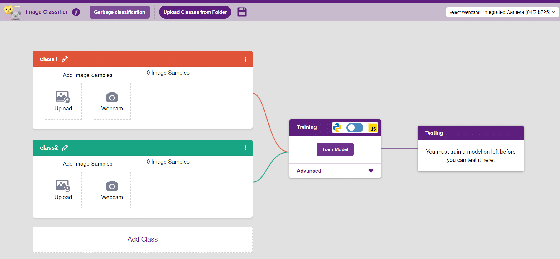
Class is the category in which the Machine Learning model classifies the images. Similar images are put in one class.
There are 2 things that you have to provide in a class:
You can perform the following operations to manipulate the data into a class.
After data is added, it’s fit to be used in model training. In order to do this, we have to train the model. By training the model, we extract meaningful information from the images, which in turn updates the weights. Once these weights are saved, we can use our model to make predictions on data previously unseen.
However, before training the model, there are a few hyperparameters that you should be aware of. Click on the “Advanced” tab to view them.
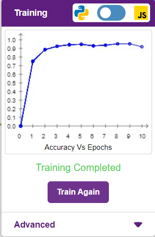
It’s a good idea to train an image classification model for a high number of epochs. The model can be trained in both JavaScript and Python. In order to choose between the two, click on the switch on top of the Training panel.
Note: These hyperparameters can affect the accuracy of your model to a great extent. Experiment with them to find what works best for your data.
The accuracy of the model should increase over time. The x-axis of the graph shows the epochs, and the y-axis represents the accuracy at the corresponding epoch. Remember, the higher the reading in the accuracy graph, the better the model. The x-axis of the graph shows the epochs, and the y-axis represents the corresponding accuracy. The range of accuracy is 0 to 1.
Here we can see the confusion matrix and training accuracy of individual classes after training.
To test the model, simply enter the input values in the “Testing” panel and click on the “Predict” button.
The model will return the probability of the input belonging to the classes.
Click on the “Export Model” button on the top right of the Testing box, and PictoBlox will load your model into the Block Coding Environment if you have opened the ML Environment in the Block Coding.
The idea is simple, we’ll add image samples in the “Backdrops” column. We’ll keep cycling through the backdrops and keep classifying the image on the stage.

You can build more applications on top of this waste classifier.
The LDR (Light Dependent Resistor) sensor is a renowned analog-type sensor that adapts its resistance according to surrounding light intensity. With its ability to fluctuate resistance based on light changes, the LDR plays a vital role in various light-sensing applications. Though typically designed as a two-pin sensor, it is also available as a three-pin module, offering enhanced features and versatility.
In this example, we embark on a fun activity using the LDR sensor and Quarky. Through this engaging experience, you will grasp essential concepts like analog and PWM signals, creating an exciting learning journey. So, let’s dive in and explore the wonders of LDR and Quarky together!
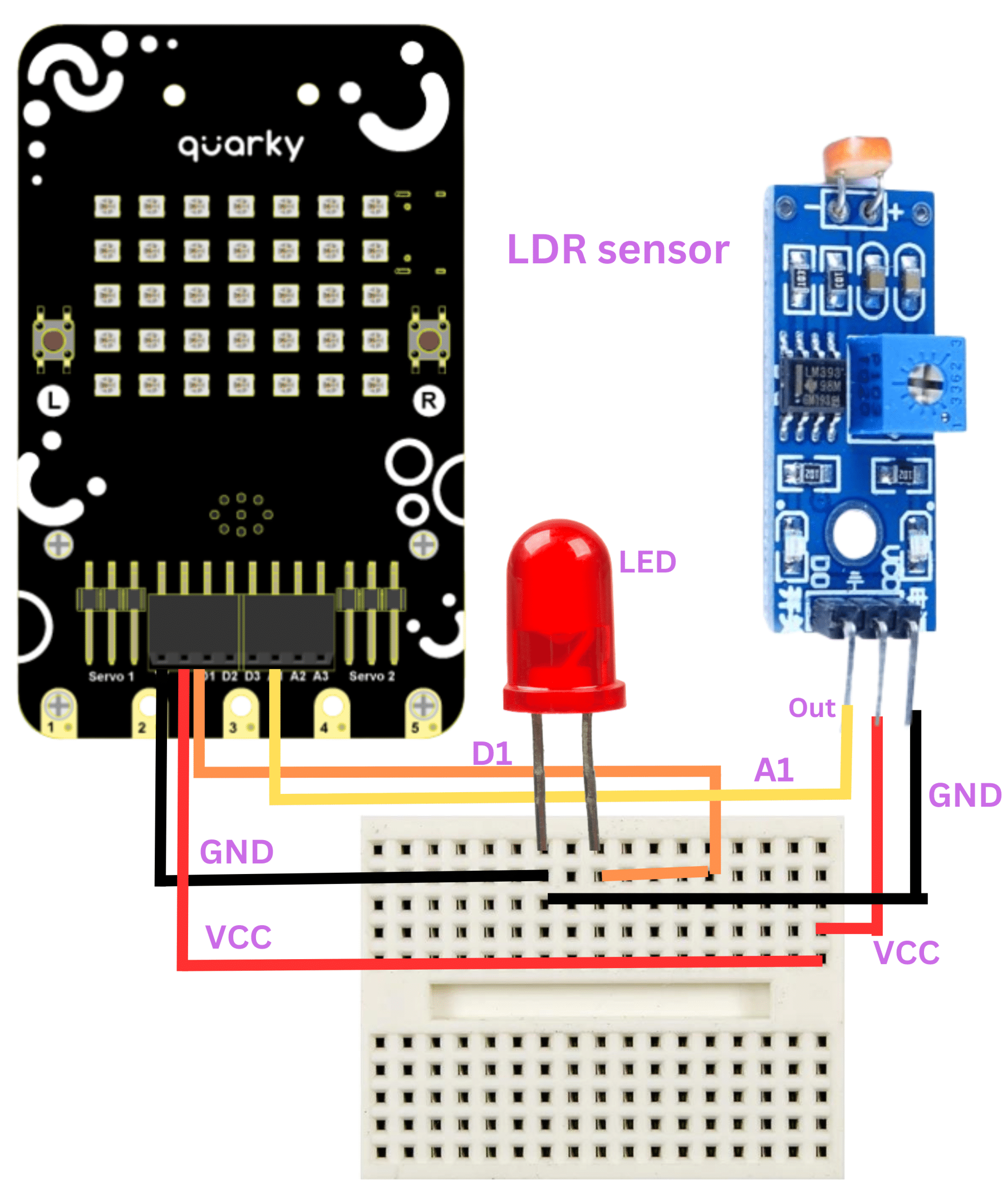
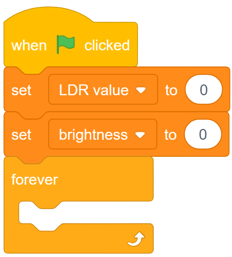
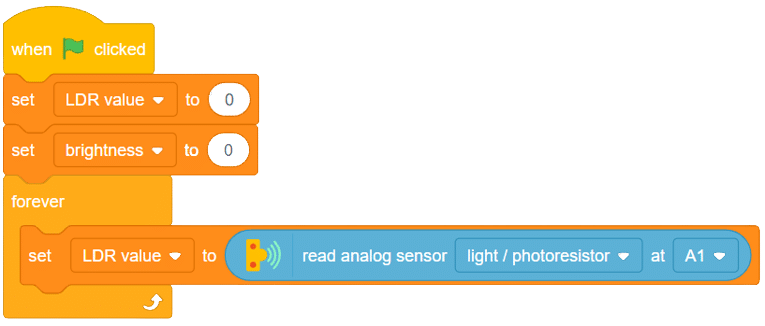
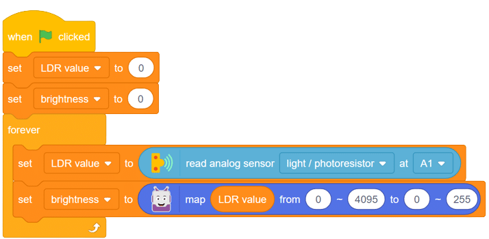
Follow these steps to implement the code using Pictoblox for Quarky and explore the behavior of the LDR sensor:

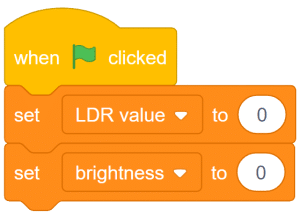
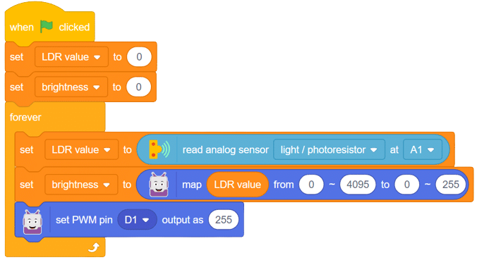
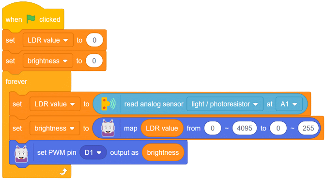
With these steps, your script is complete, and Quarky is ready to interact with the LDR sensor.
Through this exciting project, you have learned about the LDR sensor, its analog characteristics, and how Quarky can control an LED based on the light intensity sensed by the LDR. Delve deeper into the concepts of analog and PWM signals, making your robotics journey even more captivating with Quarky! Stay curious and keep exploring the endless possibilities!

Steps:
Script
The project demonstrates how to create a smart plug that can be controlled by an IoT device and that can retrieve information from the cloud. The smart plug can be used to turn lights ON and OFF.
We will be using Adafruit IO for creating a switch on the cloud. Follow the instructions:
The bulb is connected to the smart plug which is controlled with a relay.
If the relay is ON, the smart switch gets ON, turning on the light. The relay has the following connections:
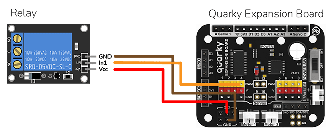
The logic is the following – We’ll connect to the Adafruit IO account, fetch the switch state from the cloud, and use and if block to turn the relay on or off accordingly.
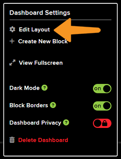
You can also make the IoT Enabled Smart Plug work independently of PictoBlox using the Upload Mode. For that switch to upload mode and replace the when green flag clicked block with when Quarky starts up the block.

You can download the code from here: IoT enabled Smart Plug – Upload Mode
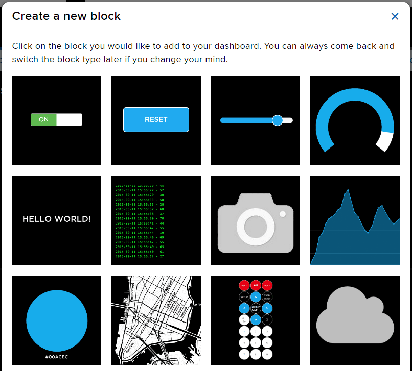
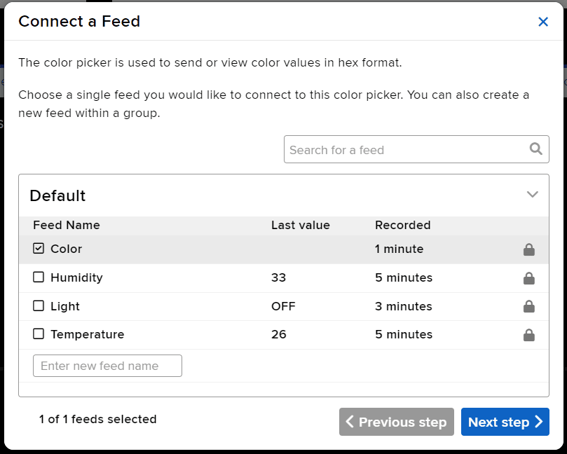
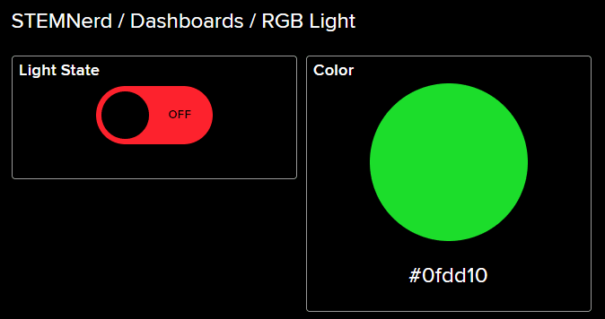
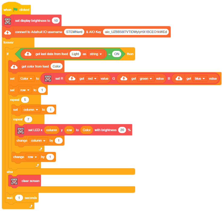
In this example, we are going to make a colored switch in Adafruit IO. Then we will make Python code for Quarky that will retrieve the color information from the cloud and make the Quarky lights ON and OFF with the selected color on the cloud.
You can find the information about your account once you log in from here:
This code creates an instance of the Quarky and AdaIO classes and connects to Adafruit IO using credentials. It then creates a loop that checks if the light is on and, if so, sets the LED on the Quarky to the color from the Adafruit IO data. If the light is not on, the display on the Quarky is cleared. The loop pauses for 1 second before repeating.
# Create an instance of the quarky class
quarky = Quarky()

# Import the time library
import time

# Create an instance of the AdaIO class
adaio = AdaIO()

# Clear the display on the quarky
quarky.cleardisplay()

# Connect to Adafruit IO using the given credentials
adaio.connecttoadafruitio("STEMNerd", "aio_UZBB56f7VTIDWyIyHX1BCEO1kWEd")

# Loop forever
while True:
  # Get the data from Adafruit IO to see if the light is on
  if (adaio.getdata("Light") == "ON"):
    # Get the color data from Adafruit IO
    adaio.getcolordata("Color")
    # Get the RGB values from the color data
    Color = [adaio.getRGB(1), adaio.getRGB(2), adaio.getRGB(3)]

    # Loop through the 5 rows and 7 columns on the quarky
    for i in range(1, 6):
      for j in range(1, 8):
        # Set the LED on the quarky to the Color with a brightness of 20
        quarky.setled(j, i, Color, 20)

  # If the light is not on, clear the display on the quarky
  else:
    quarky.cleardisplay()

  # Pause the program for 1 second
  time.sleep(1)
You can also make the script work independently of PictoBlox using the Upload Mode. For that switch to upload mode.
# Create an instance of the quarky class
from quarky import *

# Import the library
import time
import iot

# Connect to a wifi network
wifi = iot.wifi()
wifi.connecttowifi("IoT", "12345678")

# Connect to an adafruit IO account
adaio = iot.AdaIO()
adaio.connecttoadafruitio("STEMNerd", "aio_UZBB56f7VTIDWyIyHX1BCEO1kWEd")

# Clear the display on the quarky
quarky.cleardisplay()

# Loop forever
while True:
  # Check if the wifi is connected
  if wifi.iswificonnected():

    # Get the data from Adafruit IO to see if the light is on
    if (adaio.getdata("Light") == "ON"):
      # Get the color data from Adafruit IO
      adaio.getcolordata("Color")
      # Get the RGB values from the color data
      Color = [adaio.getRGB(1), adaio.getRGB(2), adaio.getRGB(3)]

      # Loop through the 5 rows and 7 columns on the quarky
      for i in range(1, 6):
        for j in range(1, 8):
          # Set the LED on the quarky to the Color with a brightness of 20
          quarky.setled(j, i, Color, 20)

    # If the light is not on, clear the display on the quarky
    else:
      quarky.cleardisplay()

    # Pause the program for 1 second
    time.sleep(1)

  else:
    # Set LED 1 to red
    quarky.setled(1, 1, [255, 0, 0], 100)
Troubleshooting:
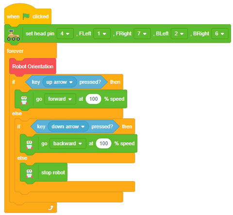
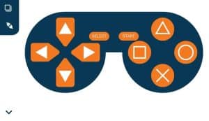
In this activity, we will control the Mars Rover according to our needs using the Dabble application on our own Devices.
We will first understand how to operate Dabble and how to modify our code according to the requirements. The following image is the front page of the Dabble Application.
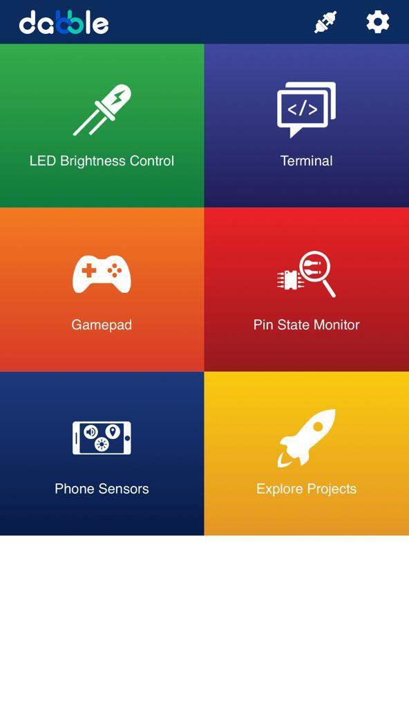
Select the Gamepad option from the Home Screen and we will then use the same gamepad to control our Mars Rover.

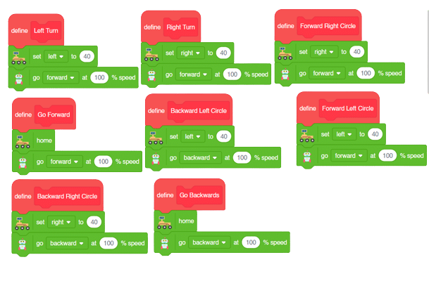
The following blocks represent the different functions that are created to control the Mars Rover for different types of motions. We will use the arrow buttons to control the basic movements.( Forward, Backward, Left, Right )
We will create our custom functions for specialized Circular motions of Mars Rover. We will use the Cross, Square, Circle, and Triangle buttons to control the Circular motions of Mars Rover.
Note: You will have to add the extensions of Mars Rover and also of Dabble to access the blocks.
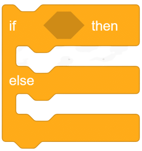
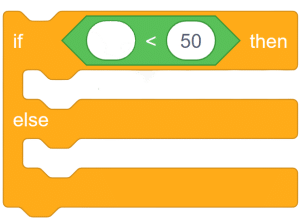
The main code will be quite simple consisting of nested if-else loops to determine the action when a specific button is pressed on the Dabble Application.
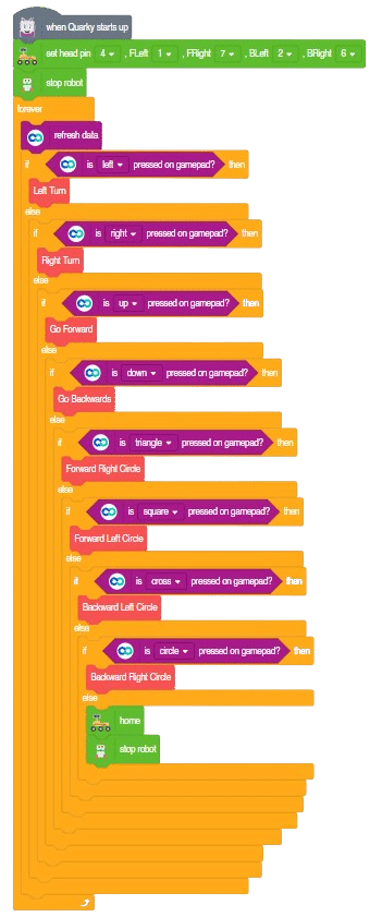
You will have to connect the Quarky with the Dabble Application on your device. Make sure Bluetooth is enabled on the device before connecting. Connect the Rover to the Dabble application after uploading the code. You will be able to connect by clicking on the plug option in the Dabble Application as seen below. Select that plug option and you will find your Quarky device. Connect by clicking on the respective Quarky.
Forward-Backward Motions:

Right-Left Motions:
Circular Left Motion:
Circular Right Motion:


Copyright 2025 – Agilo Research Pvt. Ltd. All rights reserved – Terms & Condition | Privacy Policy