The block reports the selected field data from the last read request from ThingSpeak.
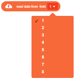
The block reports the selected field data from the last read request from ThingSpeak.
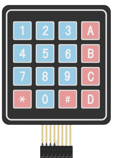
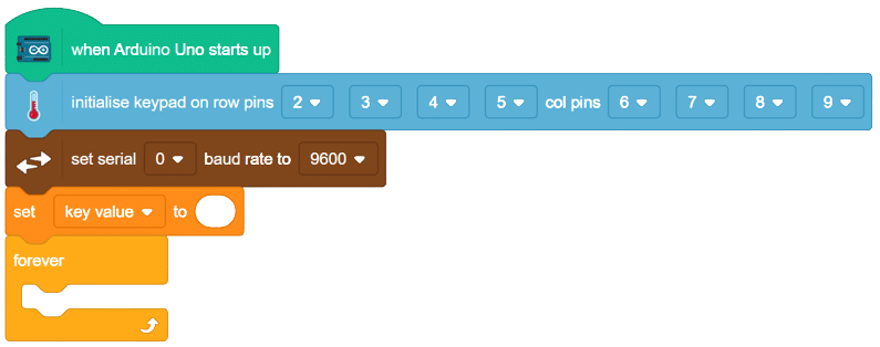
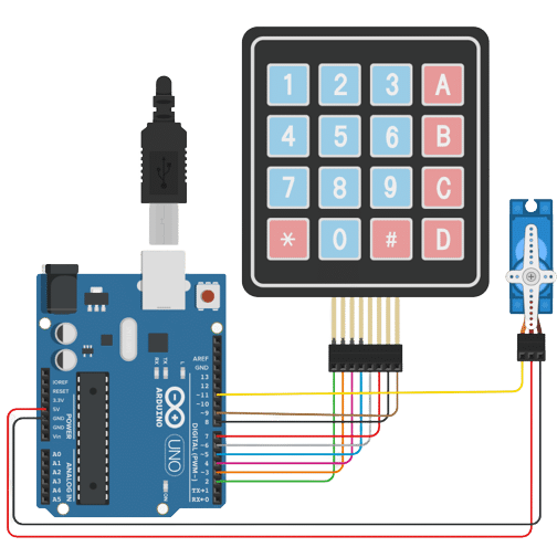
A 4×4 keypad module is an electronic input device commonly used in various applications for interfacing with microcontrollers and other digital systems. It consists of a grid of buttons arranged in a 4×4 matrix, resulting in a total of 16 buttons. Each button corresponds to a specific alphanumeric character, symbol, or command.
Working Principle: A technique called “keypad scanning” is used to read input from the keypad. The microcontroller scans the rows and columns one by one. It sets one row to HIGH and reads the column pins to detect if any button in that row is pressed. If a button is pressed, the corresponding row and column will intersect, allowing the microcontroller to determine the button that was pressed.
Applications: 4×4 keypad modules are widely used in various applications that require user input, such as security systems, door locks, industrial control panels, calculators, home automation, and more.
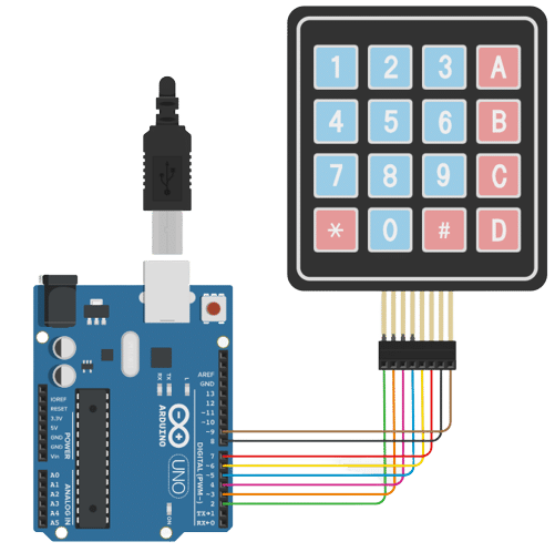
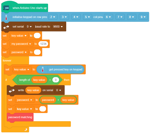
In this example, we will be interfacing the keypad module with Arduino and try to read the button value from the keypad module. let’s begin!!
Code
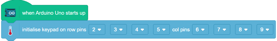
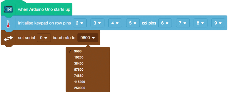
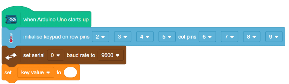
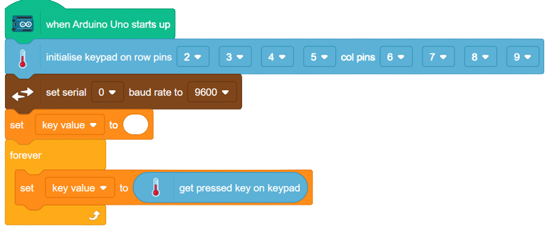
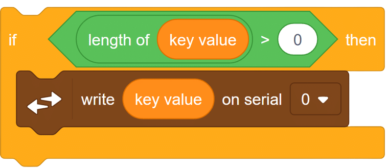
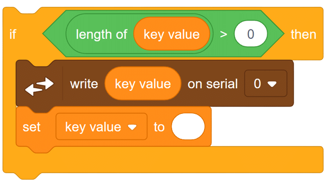
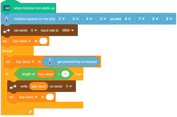
in this way we can connect our keypad module with Arduino.
OUTPUT GIF will be updated soon.
Introduction
A 4×4 keypad module is an electronic input device commonly used in various applications for interfacing with microcontrollers and other digital systems. It consists of a grid of buttons arranged in a 4×4 matrix, resulting in a total of 16 buttons. Each button corresponds to a specific alphanumeric character, symbol, or command.
Working Principle: A technique called “keypad scanning” is used to read input from the keypad. The microcontroller scans the rows and columns one by one. It sets one row to HIGH and reads the column pins to detect if any button in that row is pressed. If a button is pressed, the corresponding row and column will intersect, allowing the microcontroller to determine the button that was pressed.
Applications: 4×4 keypad modules are widely used in various applications that require user input, such as security systems, door locks, industrial control panels, calculators, home automation, and more.
In this example, we will be interfacing the keypad module with Arduino and try to read the button value from the keypad module. let’s begin!!
This is sequential example of keypad in which we are going to make a password-based door lock system. In part 1 we learned how to interface keypad with Arduino. click here to access part 1
Here we will continue updating th script that we created in part 1. Click here to access previous script.
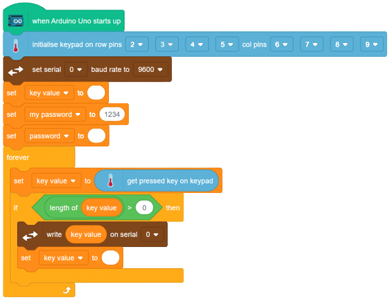
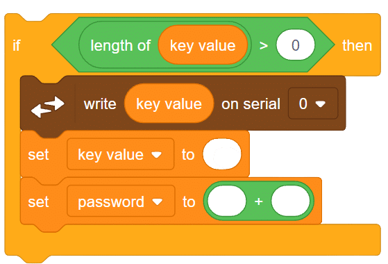
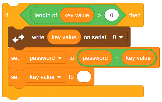
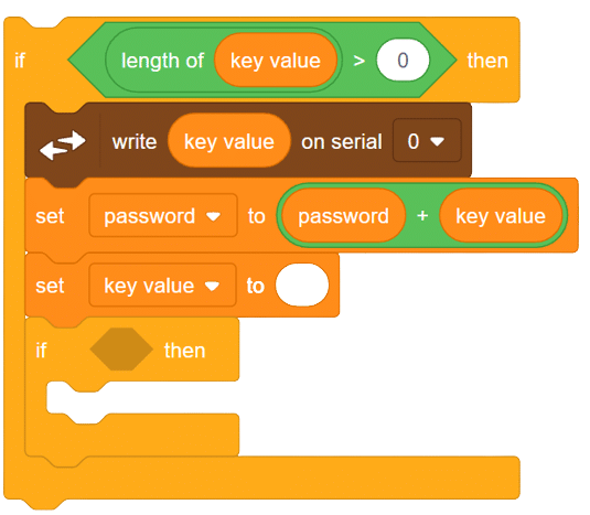
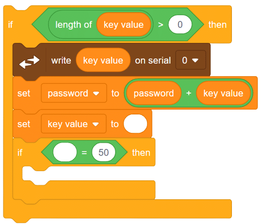
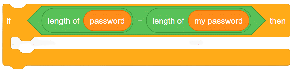
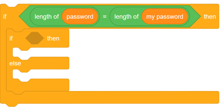
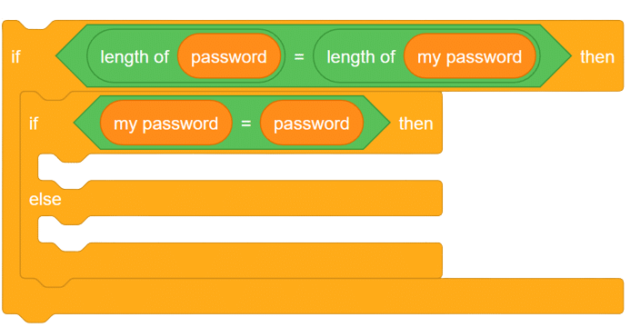
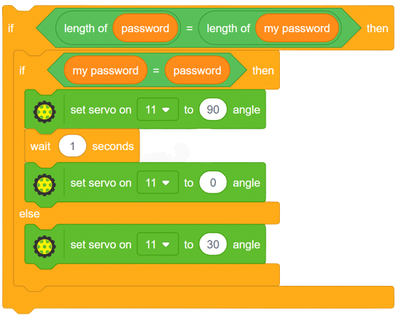
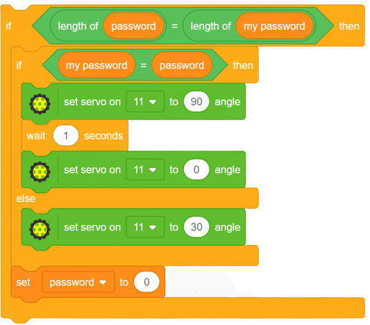
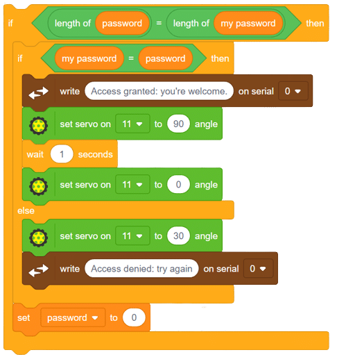
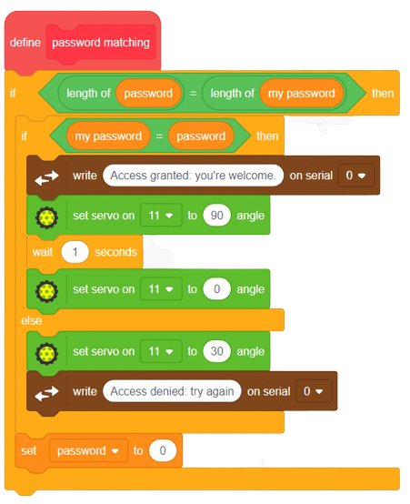
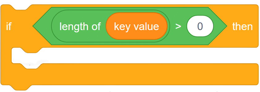
In this way, we can set any security password in our script and then can easily make a password-based security system.

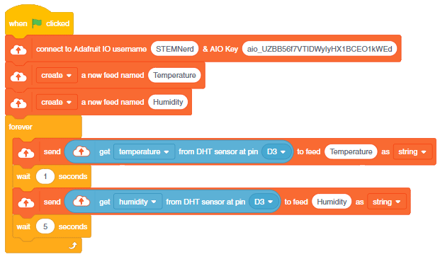
We will use the Adafruit IO cloud service to send data from a humidity and temperature sensor to the cloud. Adafruit IO is a cloud service that allows you to send data from sensors and other devices to the cloud, where it can be stored and analyzed.
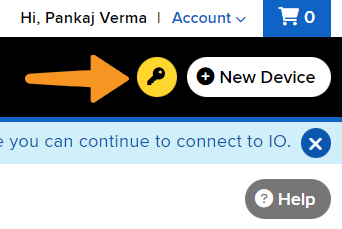
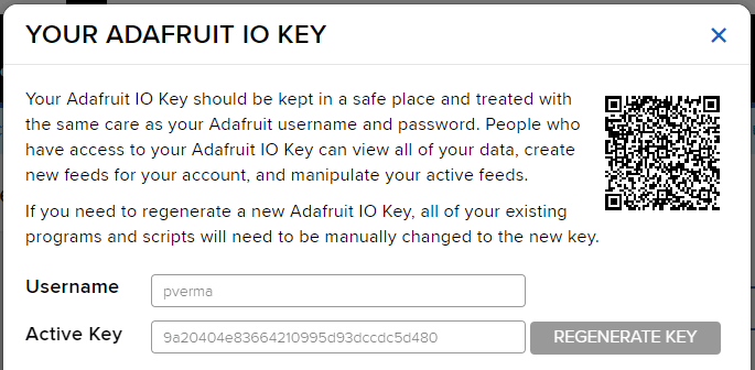
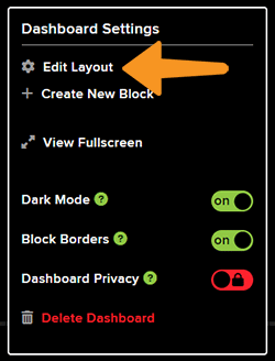
You can find the information about your account once you log in from here:

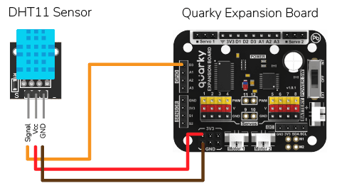
DHT sensors have 3 pins: GND, VCC, and Signal. You have to connect the following 3 pins to the Quarky Expansion Board:
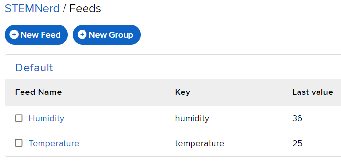
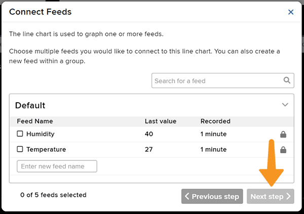
The following feeds are created:
Follow the steps:
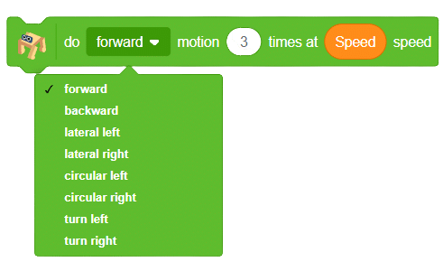
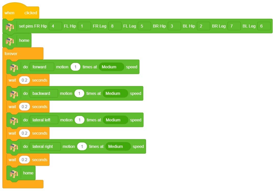
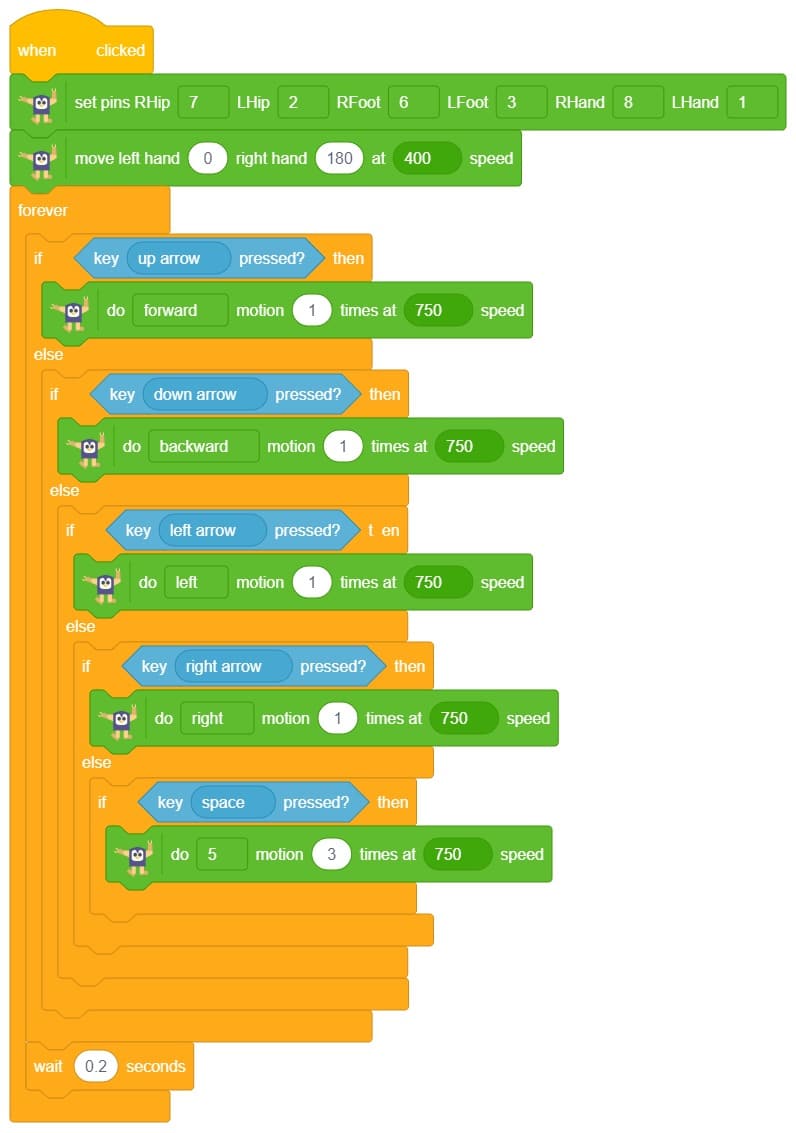
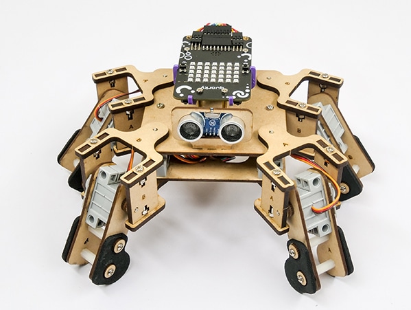
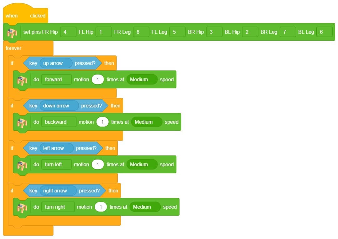
In this project, we will explain how to run predefined motions in PictoBlox for the Quadruped. The predefined motions allow users to make the robot move forward, backward, left, right, and much more.
The are eight predefined motions for Quarky in PictoBlox which can be accessed through do () motion () times at () speed block. Using the do () motion () times at () speed block, we can control the number of times the motion has to be executed.
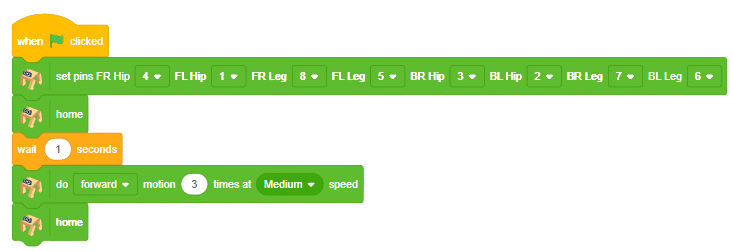
Click on the green flag to run the motion sequence.
We can also control the speed of the motion.
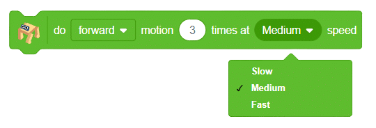
If you want to perform the motion at a different speed, then you can use a variable to define the speed.
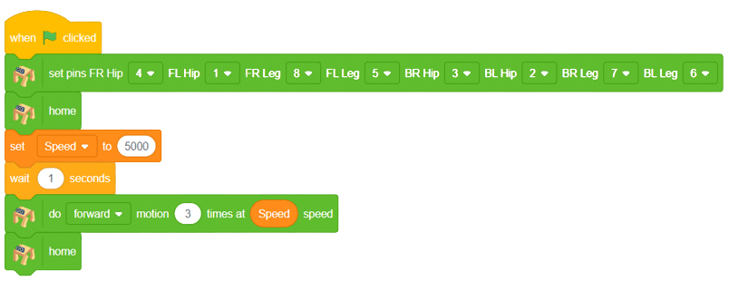
We can program a quadruped robot to move in predefined motions, such as forward, backward, left, and right


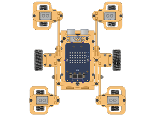
In this activity, we will make the computer program that controls the Mars Rover. It’s like a remote-control car. You can press different keys on the keyboard to make the Mars Rover move forward, backward, turn left and turn right.
In our Mars rover, there are a total of 6 motors and 5 servo motors.
The motors provide rotation to the wheels which helps the rover to attain motion in both forward and backward directions. All the left side motors (3 motors) are connected to the left motor port of Quarky and all the right side motors (3 motors) are connected to the right motor port of Quarky using a 3 port wire. This means that to control the Mars rover we have to control only 2 motors – Left and Right.
Also, there are 2 parameters to control – Direction (Forward or Backward) and Speed. With this control, the Mars rover can do all the desired motions.
The servo motors help in providing rotation to the complete wheel assembly so that the rover can change its wheel alignments and its path. These play a major role in turning cases of the Mars Rover.
We will need to turn the servo motors to the Inside Servo Position to make Mars Rover turn left and right.
sprite=Sprite('Tobi')
import time
quarky = Quarky()
rover = MarsRover(4, 1, 7, 2, 6)
while True:
  if sprite.iskeypressed("up arrow"):
	  rover.home()
	  rover.setinangle(0)
	  quarky.runtimedrobot("F",100,3)

  if sprite.iskeypressed("down arrow"):
    rover.home()
    rover.setinangle(0)
    quarky.runtimedrobot("B",100,3)

  if sprite.iskeypressed("right arrow"):
    rover.home()
    rover.setinangle(40)
    quarky.runtimedrobot("R",100,3)

  if sprite.iskeypressed("left arrow"):
    rover.home()
    rover.setinangle(40)
quarky.runtimedrobot("L",100,3)Forward-Backward Motions
Normal Right-Left Motions
A humanoid is a type of robot or artificial system that is designed to resemble a human being in its form and functionality. Humanoid robots are typically equipped with sensors, actuators, and artificial intelligence capabilities that enable them to interact with their environment and perform tasks that are similar to those of a human being. Humanoid robots are used in various fields, including robotics research, entertainment, healthcare, education, and customer service.
The Humanoid will move according to the following logic:
The program uses the up, down, left, and right arrows to control the robot and make it move forward, backward, left, and right. Every time you press one of the arrows, Humanoid will move in the direction you choose.


A humanoid is a type of robot or artificial system that is designed to resemble a human being in its form and functionality. Humanoid robots are typically equipped with sensors, actuators, and artificial intelligence capabilities that enable them to interact with their environment and perform tasks that are similar to those of a human being. Humanoid robots are used in various fields, including robotics research, entertainment, healthcare, education, and customer service.

The Humanoid will move according to the following logic:
The program uses the up, down, left, and right arrows to control the robot and make it move forward, backward, left, and right. Every time you press one of the arrows, Humanoid will move in the direction you choose.
sprite = Sprite('Tobi')
quarky = Quarky()
import time
humanoid = Humanoid(7, 2, 6, 3, 8, 1)
while True:
  if sprite.iskeypressed("up arrow"):
    humanoid.move("forward", 1000, 1)
    time.sleep(1)

  if sprite.iskeypressed("down arrow"):
    humanoid.move("backward", 1000, 1)

  if sprite.iskeypressed("left arrow"):
    humanoid.move("left", 1000, 1)

  if sprite.iskeypressed("right arrow"):
    humanoid.move("right", 1000, 1)
In this activity, we will create a custom activity where you will be able to move the Mecanum robot in a square effortlessly along with making an Axe type figure.
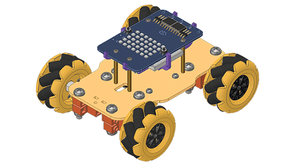
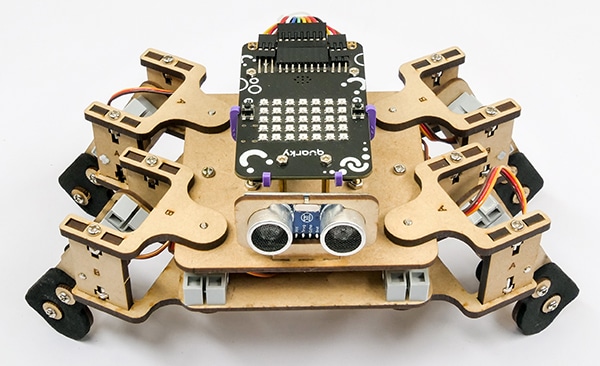
The Quarky Mecanum Wheel Robot is a type of robot that uses a special type of wheel to move. The wheel is made of four rollers mounted at 45- degree angles to the wheel’s hub. Each roller has its own motor and can spin in either direction. This allows the wheel to move in any direction, making it an ideal choice for navigating around obstacles.
Follow the steps:
The main steps would include to display the lights in arrow forms before implementing the specific move. The moves would be implemented in the following order:
Forward -> Lateral Right -> Backward -> Lateral Left.
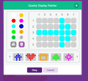
We will display the arrows with the help of Quarky LED’s and implement the code.
Example of arrow:
The main steps would include to display the lights in arrow forms before implementing the specific move. The moves would be implemented in the following order:
Forward ( 2 steps ) -> Lateral Left ( 1 step ) -> Backward Right ( 1 step ) -> Backward ( 1 step )
We will display the arrows with the help of Quarky LED’s and implement the code.
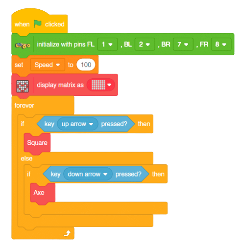
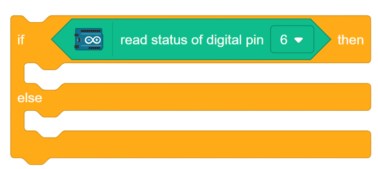
Now we will keep a specific condition on when to activate the Square Motion and when to activate the Axe Motion.
We will use the if-else conditions where on pressing the “up” arrow key, we will initiate the Square Motion and on pressing the “down” arrow key, we will initiate the Axe Motion with the help of Mecanum Robot.
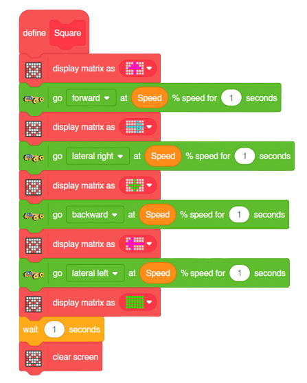
Square Motion:

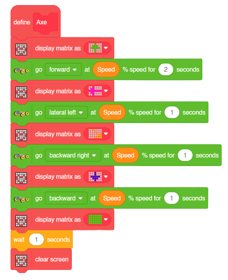
Axe Motion:
In this activity, we will create a custom activity where you will be able to move the Mecanum robot in a square effortlessly along with making an Axe type figure.
The Quarky Mecanum Wheel Robot is a type of robot that uses a special type of wheel to move. The wheel is made of four rollers mounted at 45- degree angles to the wheel’s hub. Each roller has its own motor and can spin in either direction. This allows the wheel to move in any direction, making it an ideal choice for navigating around obstacles.
Follow the steps:
The main steps would include to display the lights in arrow forms before implementing the specific move. The moves would be implemented in the following order:
Forward -> Lateral Right -> Backward -> Lateral Left.
def Square():
    quarky.drawpattern("jjjgjjjjjgggjjjgggggjjjjgjjjjjjgjjj")
    meca.runtimedrobot("forward",Speed,1)
    quarky.drawpattern("jjjjfjjjjjjffjfffffffjjjjffjjjjjfjj")
    meca.runtimedrobot("lateral right",Speed,1)
    quarky.drawpattern("jjjcjjjjjjcjjjjcccccjjjcccjjjjjcjjj")
    meca.runtimedrobot("backward",Speed,1)
    quarky.drawpattern("jjgjjjjjggjjjjgggggggjggjjjjjjgjjjj")
    meca.runtimedrobot("lateral left",Speed,1)
    quarky.drawpattern("ccccccccccccccccccccccccccccccccccc")
    time.sleep(1)
quarky.cleardisplay()The main steps would include to display the lights in arrow forms before implementing the specific move. The moves would be implemented in the following order:
Forward ( 2 steps ) -> Lateral Left ( 1 step ) -> Backward Right ( 1 step ) -> Backward ( 1 step )
We will display the arrows with the help of Quarky LED’s and implement the code.
def Axe():
    quarky.drawpattern("jjjcjjjjjcccjjjcccccjjjjcjjjjjjcjjj")
    meca.runtimedrobot("forward",Speed,2)
    quarky.drawpattern("jjgjjjjjggjjjjgggggggjggjjjjjjgjjjj")
    meca.runtimedrobot("lateral left",Speed,1)
    quarky.drawpattern("jjhjjjjjjjhjjjjjjjhjhjjjjjhhjjjhhhh")
    meca.runtimedrobot("backward right",Speed,1)
    quarky.drawpattern("jjjdjjjjjjdjjjjdddddjjjdddjjjjjdjjj")
    meca.runtimedrobot("backward",Speed,1)
    quarky.drawpattern("ccccccccccccccccccccccccccccccccccc")
    time.sleep(1)
quarky.cleardisplay()Now we will keep a specific condition on when to activate the Square Motion and when to activate the Axe Motion.
We will use the if-else conditions where on pressing the “up” arrow key, we will initiate the Square Motion and on pressing the “down” arrow key, we will initiate the Axe Motion with the help of Mecanum Robot.
sprite = Sprite('Tobi')
quarky=Quarky()
import time

def Square():
    quarky.drawpattern("jjjgjjjjjgggjjjgggggjjjjgjjjjjjgjjj")
    meca.runtimedrobot("forward",Speed,1)
    quarky.drawpattern("jjjjfjjjjjjffjfffffffjjjjffjjjjjfjj")
    meca.runtimedrobot("lateral right",Speed,1)
    quarky.drawpattern("jjjcjjjjjjcjjjjcccccjjjcccjjjjjcjjj")
    meca.runtimedrobot("backward",Speed,1)
    quarky.drawpattern("jjgjjjjjggjjjjgggggggjggjjjjjjgjjjj")
    meca.runtimedrobot("lateral left",Speed,1)
    quarky.drawpattern("ccccccccccccccccccccccccccccccccccc")
    time.sleep(1)
    quarky.cleardisplay()

def Axe():
    quarky.drawpattern("jjjcjjjjjcccjjjcccccjjjjcjjjjjjcjjj")
    meca.runtimedrobot("forward",Speed,2)
    quarky.drawpattern("jjgjjjjjggjjjjgggggggjggjjjjjjgjjjj")
    meca.runtimedrobot("lateral left",Speed,1)
    quarky.drawpattern("jjhjjjjjjjhjjjjjjjhjhjjjjjhhjjjhhhh")
    meca.runtimedrobot("backward right",Speed,1)
    quarky.drawpattern("jjjdjjjjjjdjjjjdddddjjjdddjjjjjdjjj")
    meca.runtimedrobot("backward",Speed,1)
    quarky.drawpattern("ccccccccccccccccccccccccccccccccccc")
    time.sleep(1)
    quarky.cleardisplay()


meca=Mecanum(1,2,7,8)


Speed = 100
quarky.drawpattern("jjjjjjjjjjjjjjjjjjjjjjjjjjjjjjjjjjj")
while True:
  if sprite.iskeypressed("up arrow"):
    Square()
  else:
    if sprite.iskeypressed("down arrow"):
Axe()Square Motion:
Axe Motion:
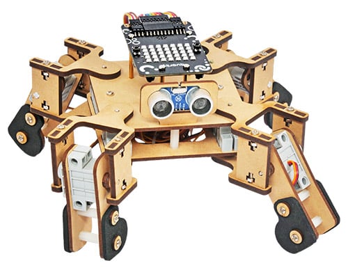
The project demonstrates how to make the crawling motion with Quadruped using individual servo control.
For this project, we are using the moveall(servo angles = [90,90,90,90,90,90,90,90], time = 1000) code that sets the servo motors of the quadruped to the specified angles at the specified speed.
quad.moveall([90,90,90,90,90,90,90,90],Speed)There are four positions of the robot we are going to make to create the crawling motion:
quad.moveall([60,120,0,180,60,120,180,0],Speed)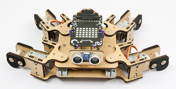
quad.moveall([30,150,60,120,60,120,120,60],Speed)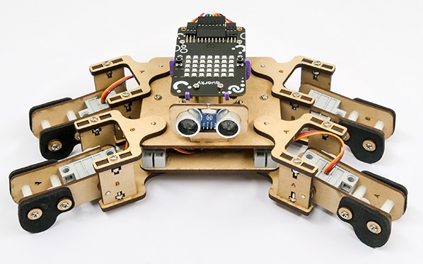
quad.moveall([120,60,60,120,120,60,120,60],Speed)
quad.moveall([120,60,0,180,150,30,180,0],Speed)
sprite = Sprite('Tobi')
quarky = Quarky()

quad=Quadruped(4,1,8,5,3,2,7,6)

Speed = 250
while True:
	quad.moveall([60,120,0,180,60,120,180,0],Speed)
	quad.moveall([30,150,60,120,60,120,120,60],Speed)
	quad.moveall([120,60,60,120,120,60,120,60],Speed)
	quad.moveall([120,60,0,180,150,30,180,0],Speed)
In this project, we will explain how to run predefined motions in PictoBlox for the Quadruped. The predefined motions allow users to make the robot move forward, backward, left, right, and much more.
sprite = Sprite('Tobi')
quirky = Quarky()
import time
quad=Quadruped(4,1,8,5,3,2,7,6)

while True:
  quad.home()
  time.sleep(0.5)
  quad.move("forward",1000,2)
  time.sleep(0.5)
  quad.move("backward",1000,2)
  time.sleep(0.5)
  quad.move("lateral left",1000,2)
  time.sleep(0.5)
  quad.move("lateral Right",1000,2)
  quad.home()

The Language Translator with ChatGPT and Speech Recognition is a system that helps people communicate across languages by providing real-time translation and conversation support. It combines language translation, chatbot capabilities, and speech recognition to facilitate multilingual communication.
Language Translator Using ChatGPT is a project that trains the ChatGPT language model with multilingual data to enable it to understand and translate text between different languages. It utilizes ChatGPT’s natural language processing abilities to generate human-like responses, making it ideal for building a language translation system. The training data includes sentence pairs in different languages and their corresponding translations.
The code represents a conversation between the sprite character “Tobi” and the AI models. The sprite asks the user for a definition, the user responds, the AI generates a result based on the response, and the sprite says and speaks the result.
Follow the steps below:
sprite = Sprite('Tobi')
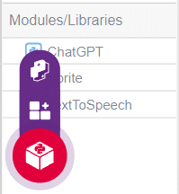
gpt = ChatGPT()
speech = TexttoSpeech()
sprite.input("Provide a Sentece i will traslated into Hindi ")
l = str(sprite.answer())
gpt.translatelanguage(l,"hindi")
result=gpt.chatGPTresult()
sprite.say(result,2)
speech.speak(result)
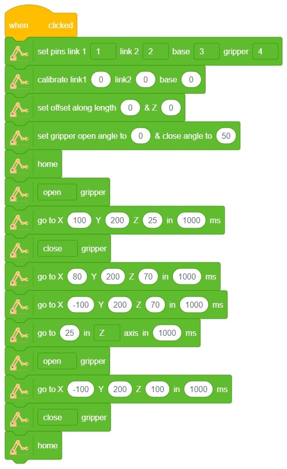
A pick-and-place robotic arm is a mechanical system designed to perform the task of picking up objects from one location and placing them in another. It consists of multiple segments connected, similar to a human arm, and is equipped with motors, sensors, and grippers.
The robotic arm is programmed to move in a precise and controlled manner. It can be guided by various input methods, such as a computer interface or remote control. The arm uses its grippers to grasp objects securely, and then it can move them to a different location.
Pick-and-place robotic arms are commonly used in industries such as manufacturing, logistics, and assembly lines. They automate repetitive tasks that involve moving objects, saving time and reducing the risk of human error. These robotic arms can handle a wide range of objects, from small components to larger items, with accuracy and efficiency.

The gripper is used to pick and place any object. We are going to learn how to control it in this example.
The gripper has 2 states:
Now there are many methods to control the gripper. We will discuss 2 methods:
Let’s see how they work.
Logic
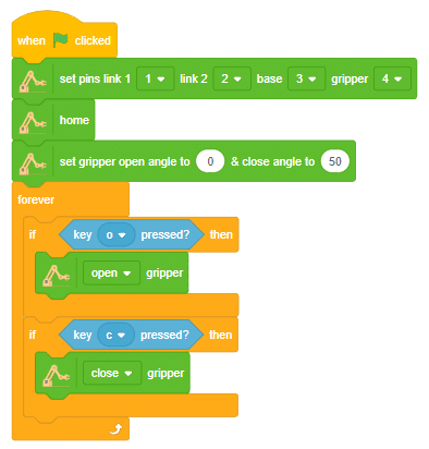
Run the code to check the working of the gripper:

Logic
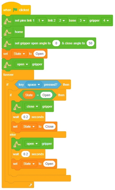
In this project, we learned how to control the gripper using two different methods. The first was 2-key control, which activated when either the ‘o’ or ‘c’ key was pressed. The second was 1-key control, which activated when the ‘space’ bar was pressed. Both were able to accurately open and close the gripper and can be used in robotics applications.

A wireless controlled robotic arm revolutionizes how we interact with robots by eliminating the need for physical connections. Users can remotely manipulate the arm’s movements without being tied to it, offering flexibility and convenience.
Wireless control allows operating the robotic arm from a distance, ensuring safety and versatility. It can be controlled through a smartphone app, remote control, or computer software. Wireless communication protocols like Bluetooth or Wi-Fi enable seamless transmission of commands.
These robotic arms have applications in industrial automation, healthcare, research, and education. They provide precise movements for delicate tasks and complex maneuvers, such as object manipulation, surgeries, or hazardous environment exploration.
Wireless control enables automation, remote operation, and collaboration. Multiple arms can be controlled simultaneously, enhancing productivity and enabling cooperative tasks. Integration with smart systems and the Internet of Things (IoT) ecosystem is facilitated.
sprite = Sprite('Tobi')

import time

roboticArm = RoboticArm(1,2,3,4)


roboticArm.sethome()
roboticArm.setgripperangle(90,148)
while True:
	if sprite.iskeypressed("up arrow"):
		roboticArm.movebyinoneaxis(10,"X",10)

	if sprite.iskeypressed("down arrow"):
			roboticArm.movebyinoneaxis(-10,"X",1000)

	if sprite.iskeypressed("left arrow"):
	 roboticArm.movebyinoneaxis(10,"Y",1000)

	if sprite.iskeypressed("right arrow"):
		roboticArm.movebyinoneaxis(-10,"Y",1000)

	if sprite.iskeypressed("o"):
	 roboticArm.movebyinoneaxis(10,"Z",1000)

	if sprite.iskeypressed("c"):
roboticArm.movebyinoneaxis(-10,"Z",1000)User control the robotic arm’s movements using arrow keys for X and Y axes and the ‘o‘ and ‘c‘ keys for the Z-axis. The specific movements and functions may vary depending on the implementation of the Roboti Arm class.

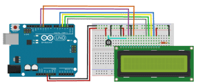
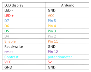
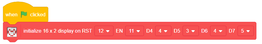
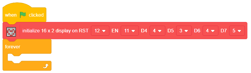
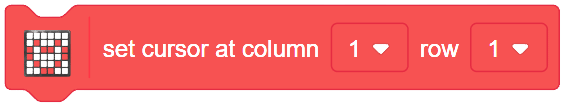
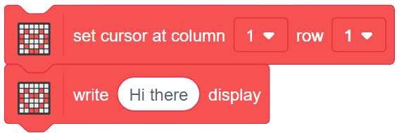
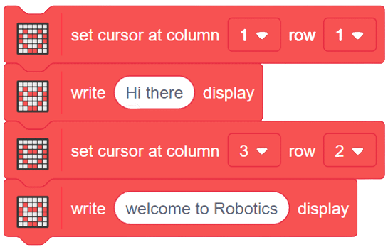
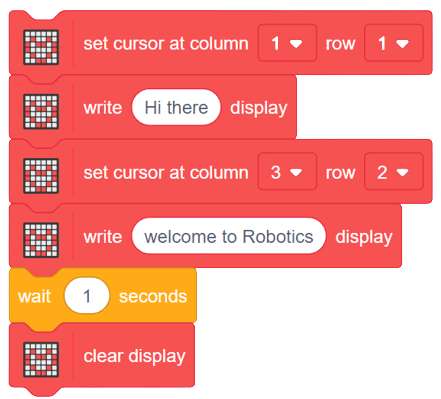
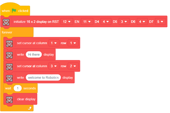
The liquid crystal display uses the property of light monitoring of liquid crystal and they do not emit the light directly. The Liquid crystal display is a flat panel display or the electronic visual display. With low information content the LCD’ s are obtained in the fixed image or the arbitrary image which are displayed or hidden like present words, digits, or 7 segment display. The arbitrary images are made up of large no of small pixels and the element has larger elements. A 16×2 LCD means it can display 16 characters per line and there are 2 such lines. In this LCD each character is displayed in a 5×7 pixel matrix. The 16 x 2 intelligent alphanumeric dot matrix display is capable of displaying 224 different characters and symbols.

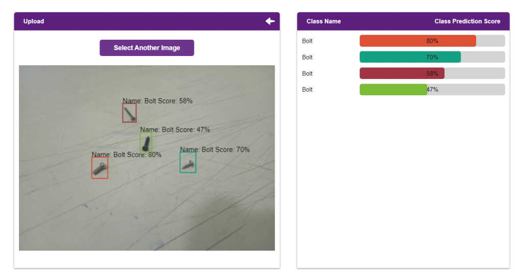
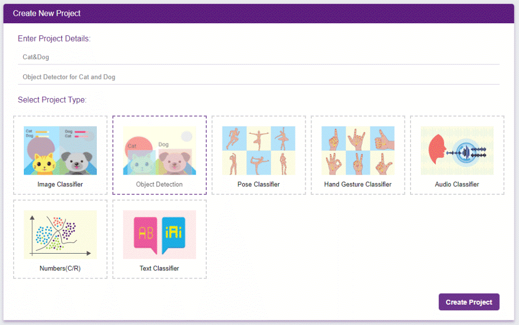
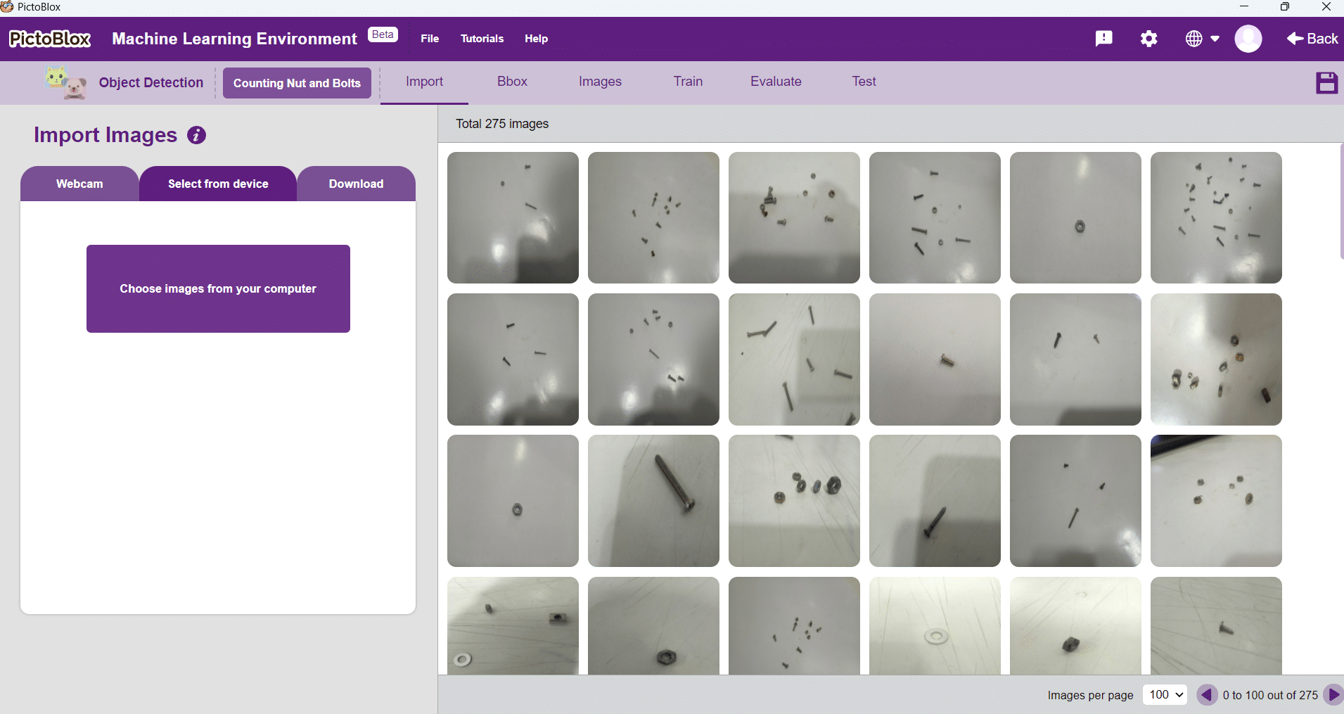
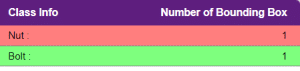
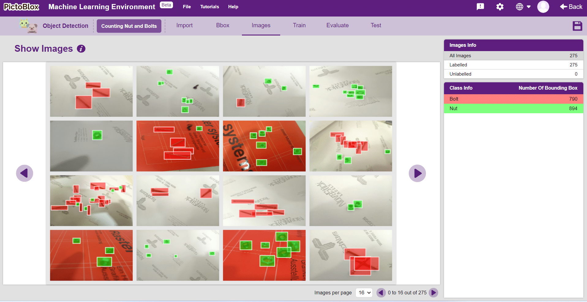
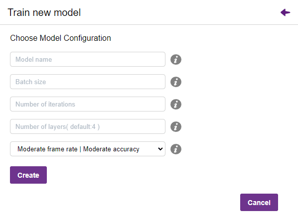
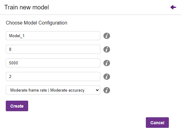
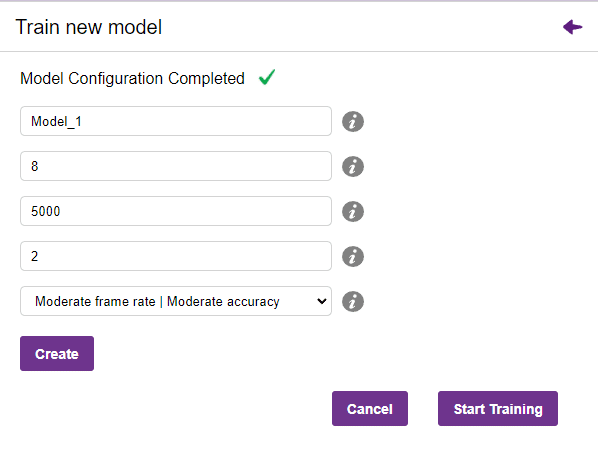
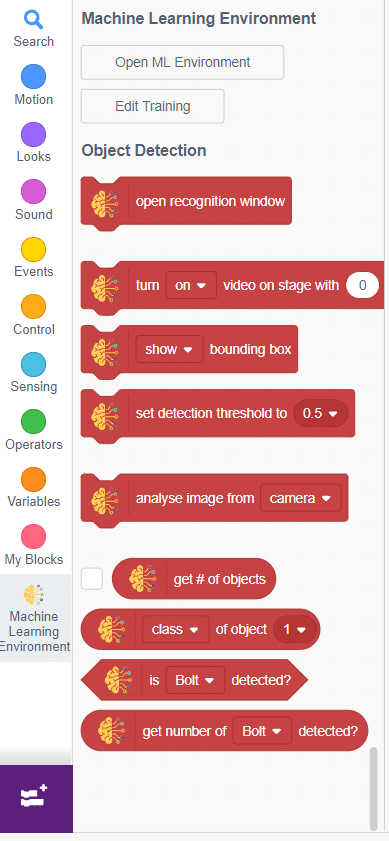
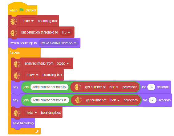
In this example project we are going to create a Machine Learning Model which can count number of nuts and bolts from the camera feed or images.
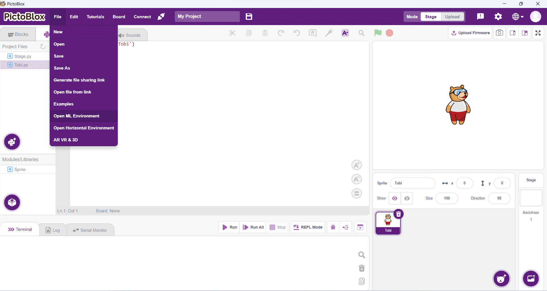
Object Detection is an extension of the ML environment that allows users to detect images and making bounding box into different classes. This feature is available only in the desktop version of PictoBlox for Windows, macOS, or Linux. As part of the Object Detection workflow, users can add classes, upload data, train the model, test the model, and export the model to the Block Coding Environment.

Alert: The Machine Learning Environment for model creation is available in the only desktop version of PictoBlox for Windows, macOS, or Linux. It is not available in Web, Android, and iOS versions.
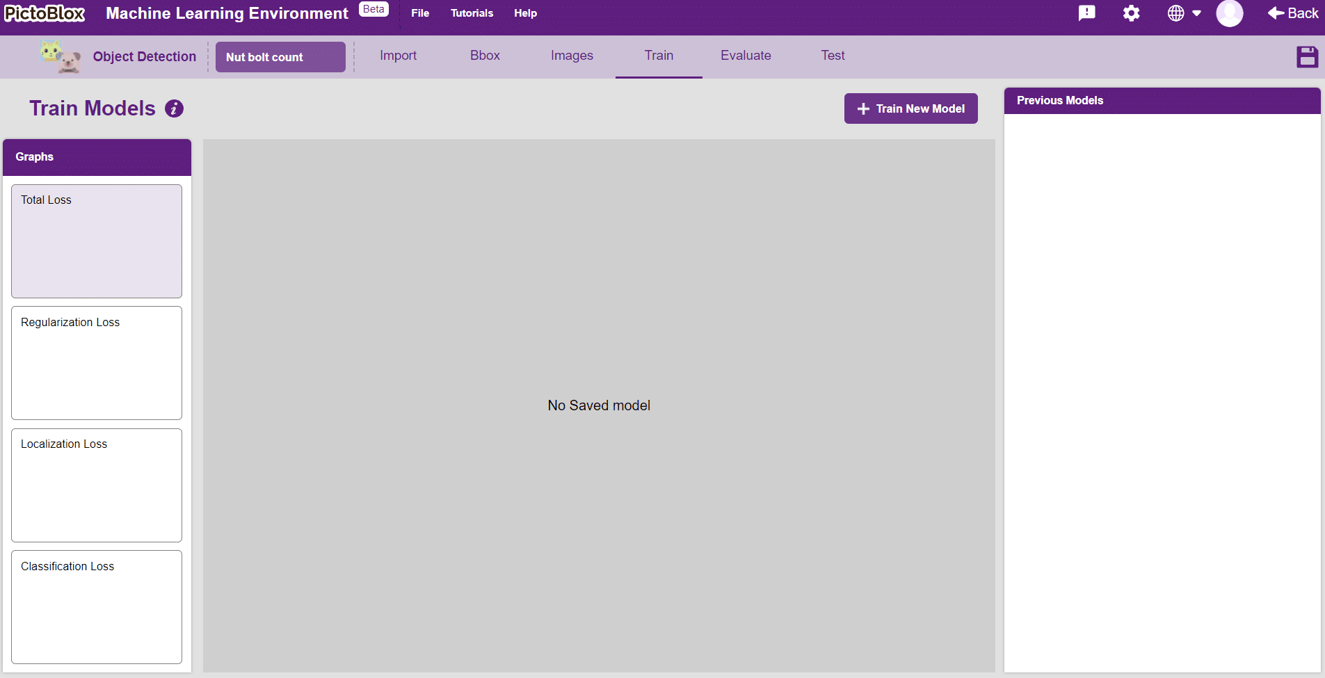
Follow the steps below:
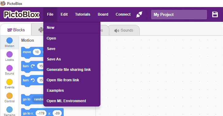
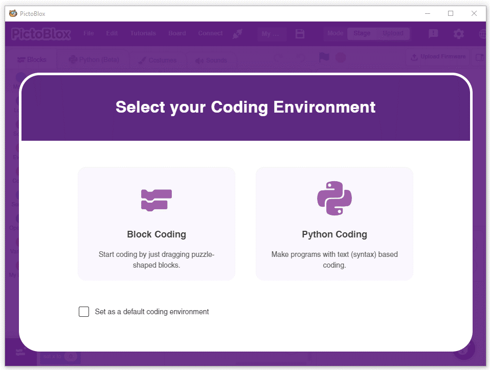
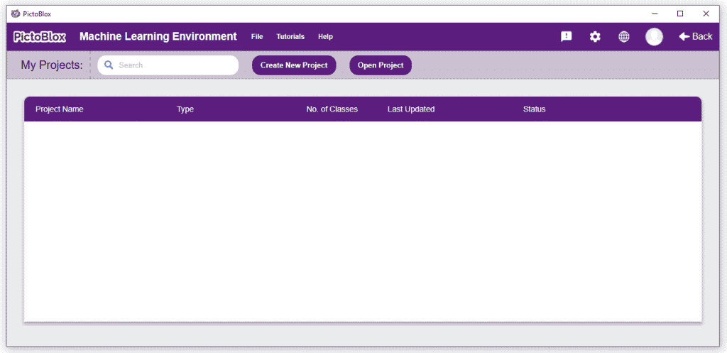
You shall see the Object Detection workflow. Your environment is all set.
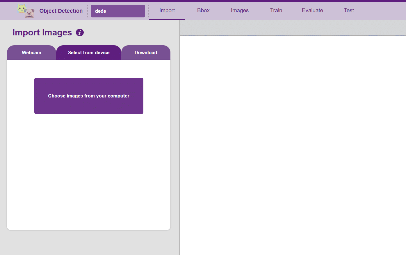
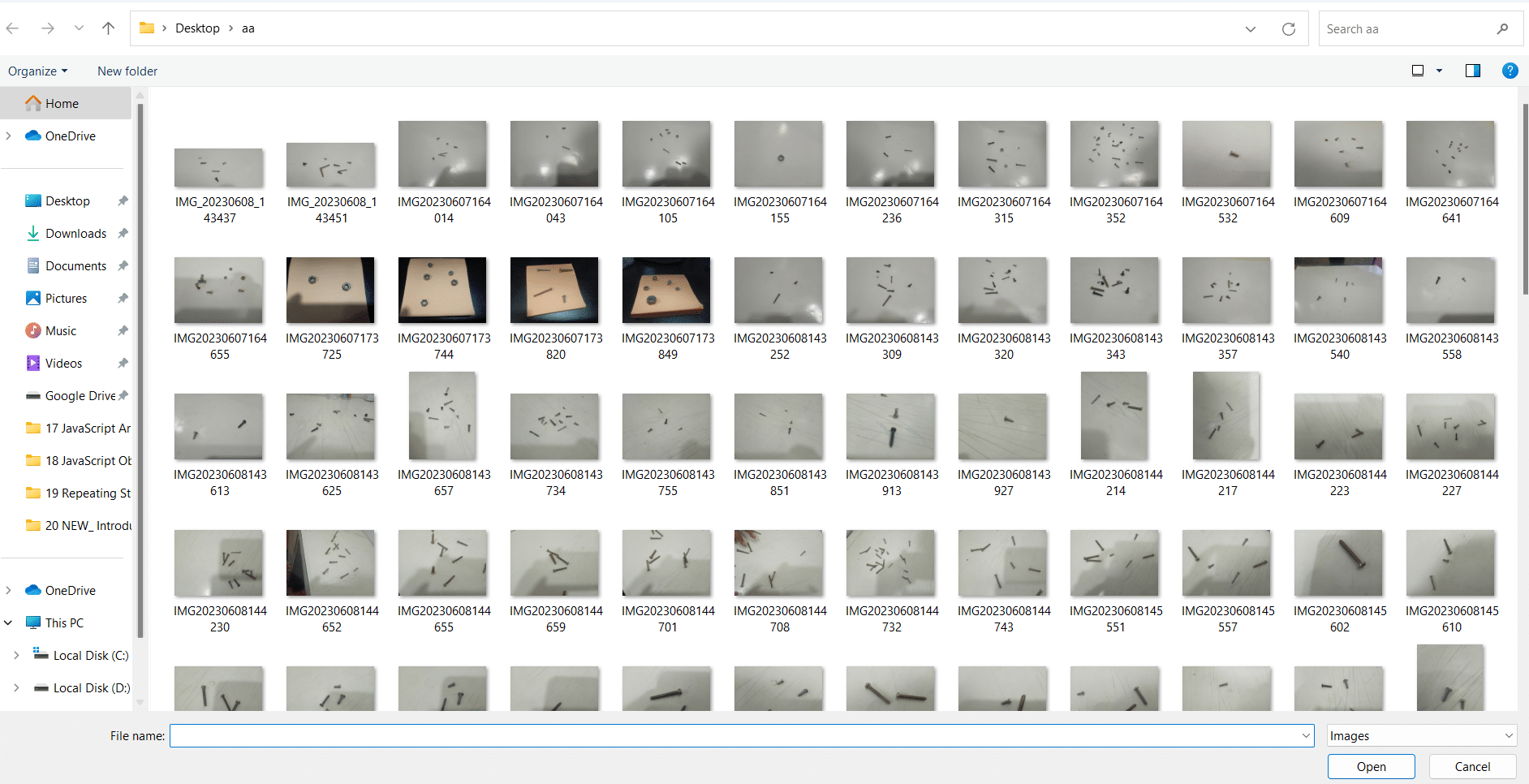
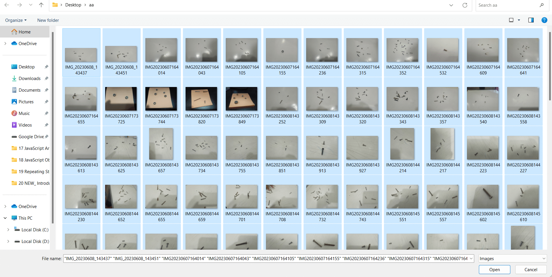
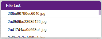
Uploading images from your device’s hard drive
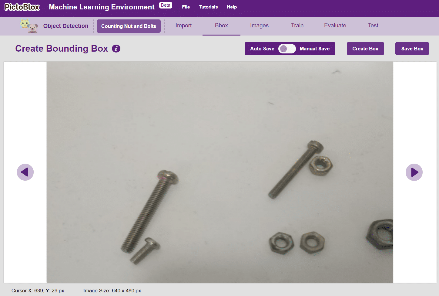
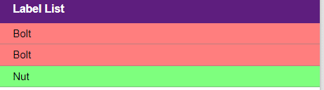
Notes: Notice how the targets are marked with a bounding box. The labels appear in the “Label List” column on the right.
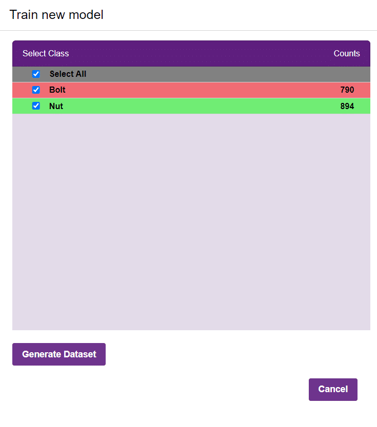
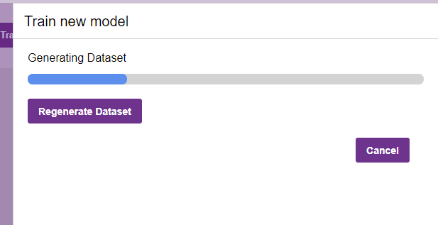
In Object Detection, the model must locate and identify all the targets in the given image. This makes Object Detection a complex task to execute. Hence, the hyperparameters work differently in the Object Detection Extension.
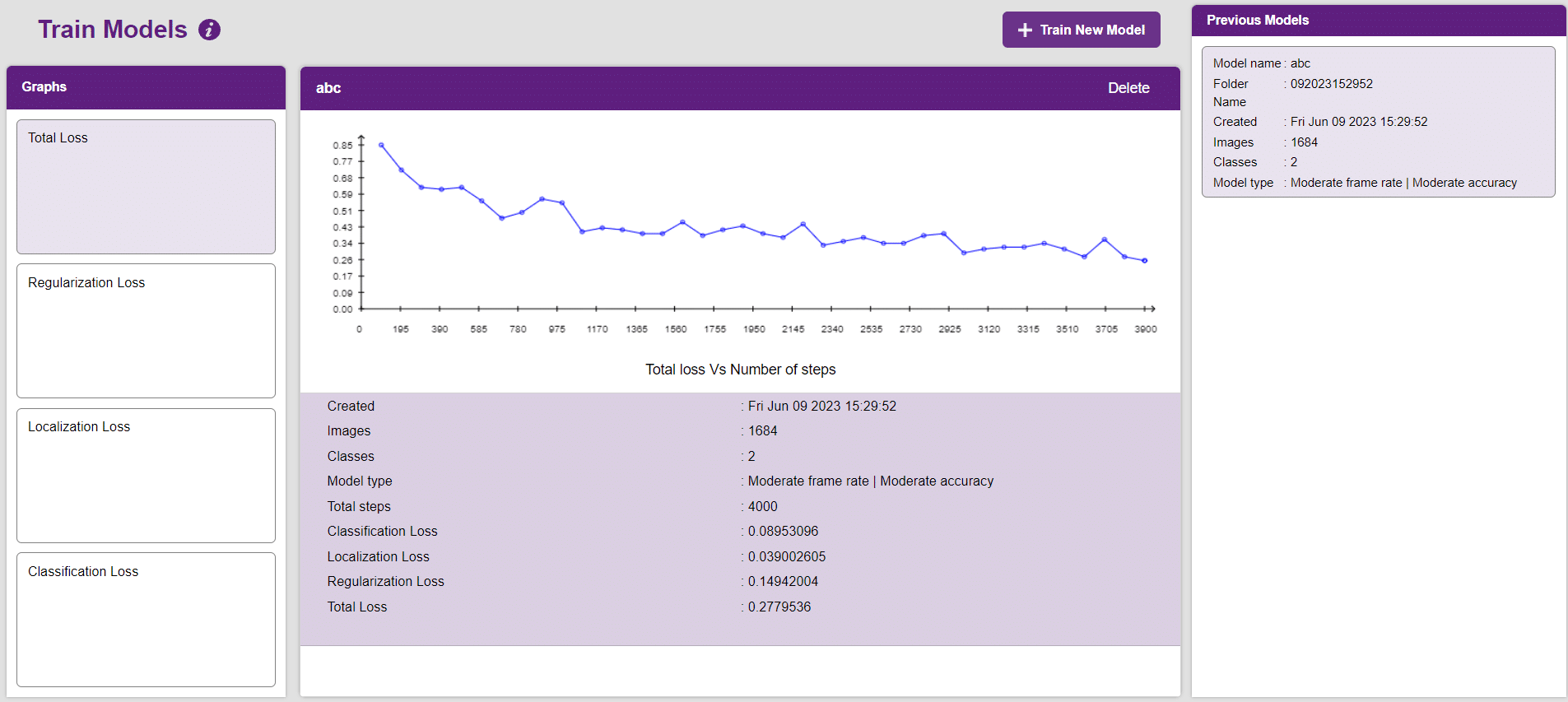
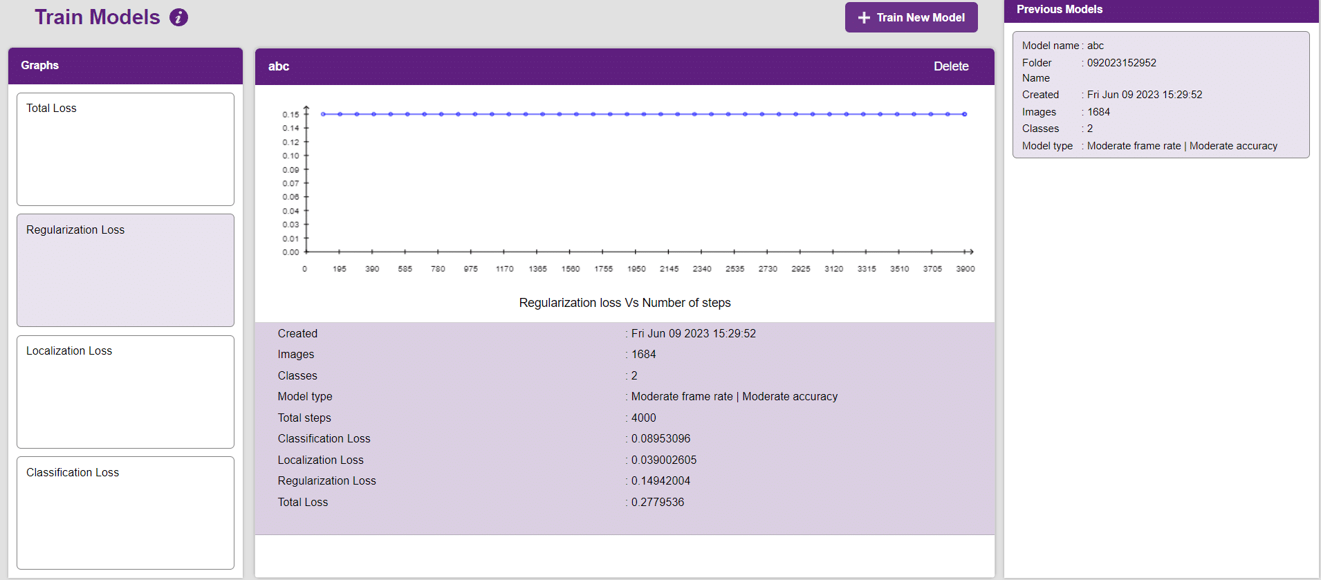
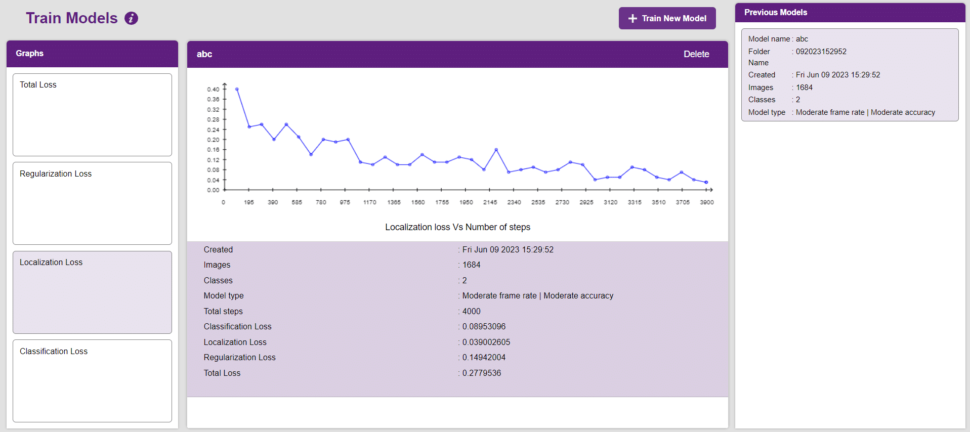
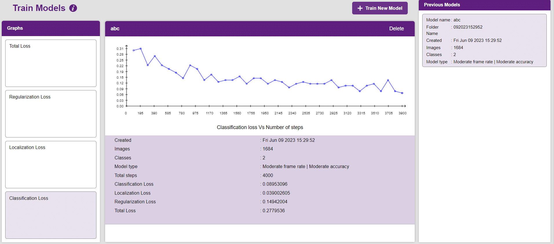
Now, let’s move to the “Evaluate” tab. You can view True Positives, False Negatives, and False Positives for each class here along with metrics like Precision and Recall.
The model will be tested by uploading an Image from device:
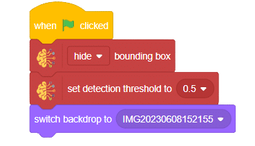
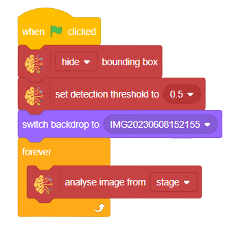
Click on the “PictoBlox” button, and PictoBlox will load your model into the Block Coding Environment if you have opened the ML Environment in the Block Coding.
The idea is simple, we’ll add image samples in the “Backdrops” column. We’ll keep cycling through the backdrops and keep predicting the image on the stage.
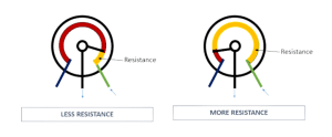
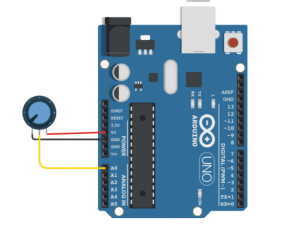
A potentiometer is a crucial three-terminal resistor featuring a sliding or rotating contact that forms an adjustable voltage divider. When using only two terminals (one end and the wiper), it functions as a variable resistor or rheostat. The potentiometer’s three pins consist of two connected to the resistive element (blue and green) and one connected to the adjustable wiper (black). The potentiometer can serve as a rheostat to vary resistance or as a voltage divider. The position of the wiper determines the amount of resistance imposed on the circuit, as demonstrated in the figure below.

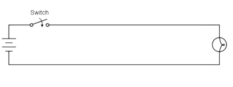
A switch is an essential electrical component that can disconnect or connect the conducting path in an electrical circuit, effectively interrupting or diverting the electric current. It plays a critical role in ON-OFF control for various applications across industries such as telecommunications, industrial control equipment, commercial devices, and home appliances.
The primary application of switches is to enable the ON-OFF control of circuits. They are widely used in industries including:
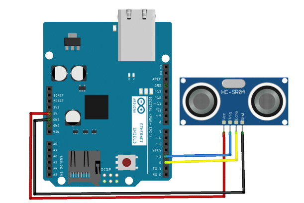
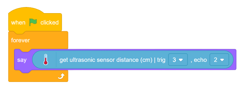
An ultrasonic sensor is an electronic device that measures the distance of a target object by emitting ultrasonic sound waves, and converts the reflected sound into an electrical signal.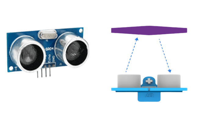
Ultrasonic waves travel faster than the speed of audible sound (i.e. the sound that humans can hear). Ultrasonic sensors have two main components: the transmitter (which emits the sound using piezoelectric crystals) and the receiver (which encounters the sound after it has traveled to and from the target). It works by emitting a sound wave that travels through the air and bounces back to the sensor if it encounters an obstacle or object.

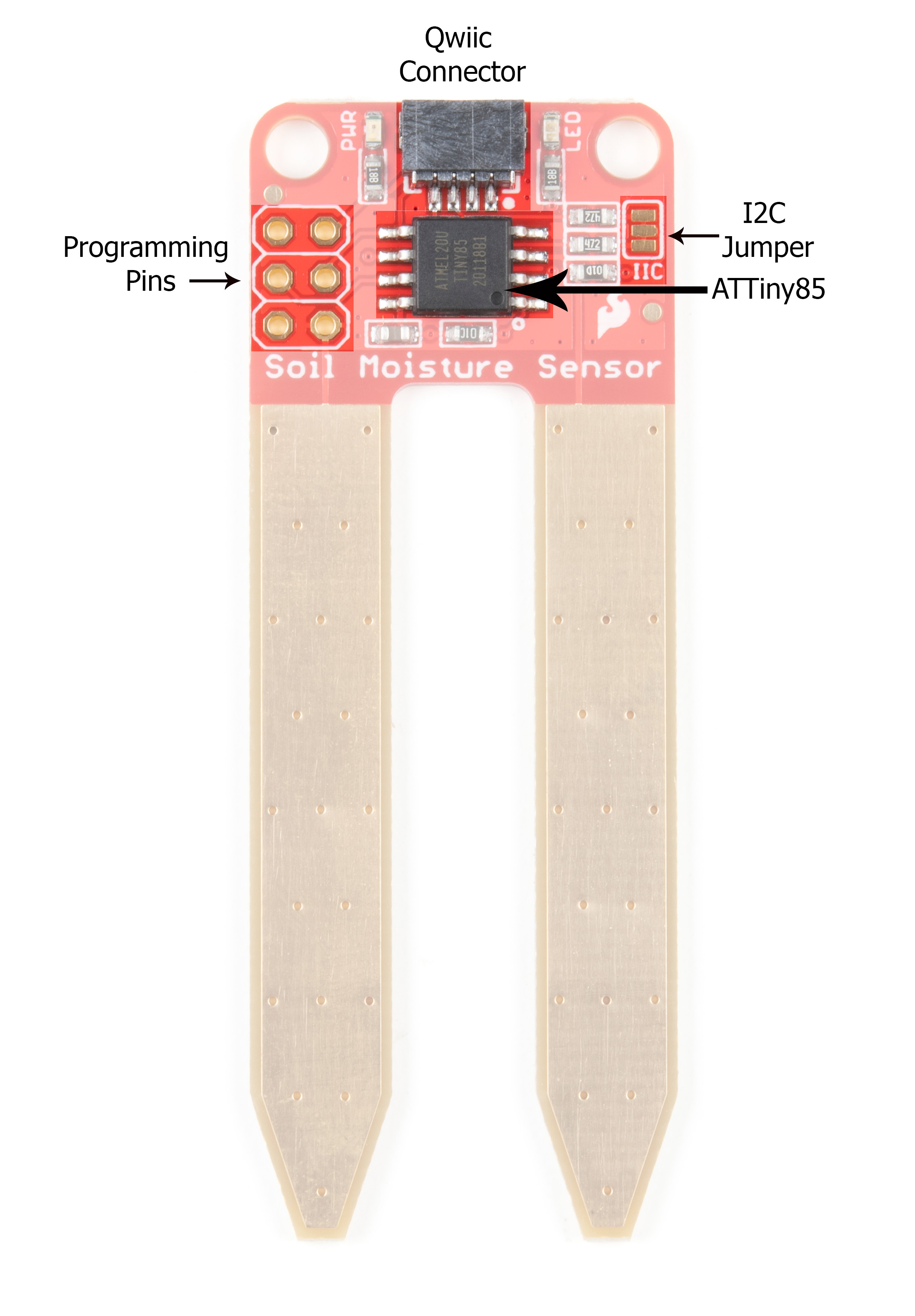
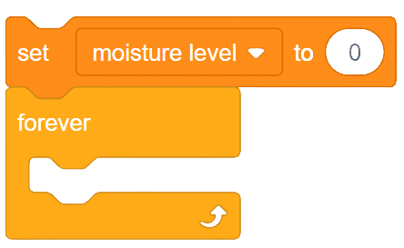
The soil moisture sensor is a valuable tool used to determine the moisture content in the soil, crucial for efficient gardening, farming, and agricultural practices. This analog sensor generates varying output values depending on the moisture level present in the soil. Typically, it operates as a two-pin circuit, with these pins responsible for powering up the sensor module. To obtain soil moisture readings, a voltage divider circuit is employed on the negative pin of the sensor, resulting in a signal pin that provides the moisture level data. Alternatively, some sensor modules come with a controller circuit that automatically converts the 2-pin connection into a 3-pin output, simplifying the process of accessing moisture values.
Below is a simple circuit diagram and code to get you started with monitoring soil moisture using an Arduino board. By following these steps, you can create your own moisture monitoring system with ease. Let’s begin!

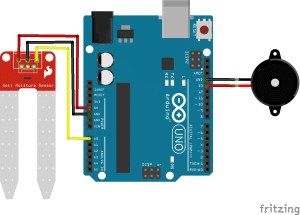
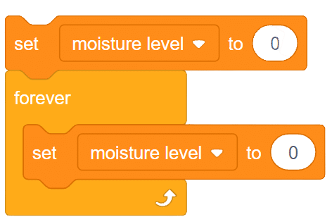
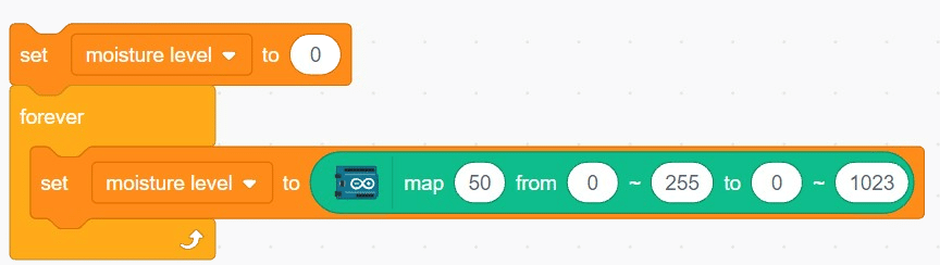
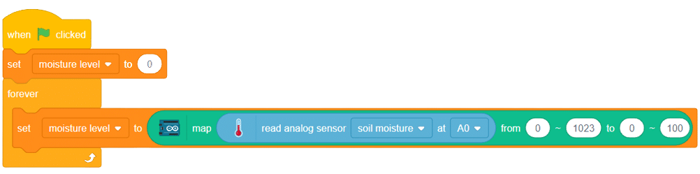
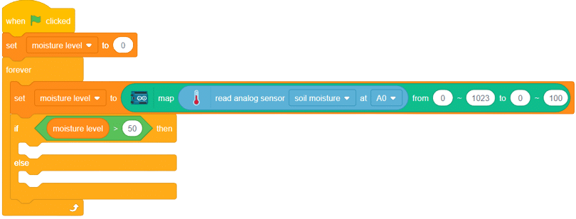
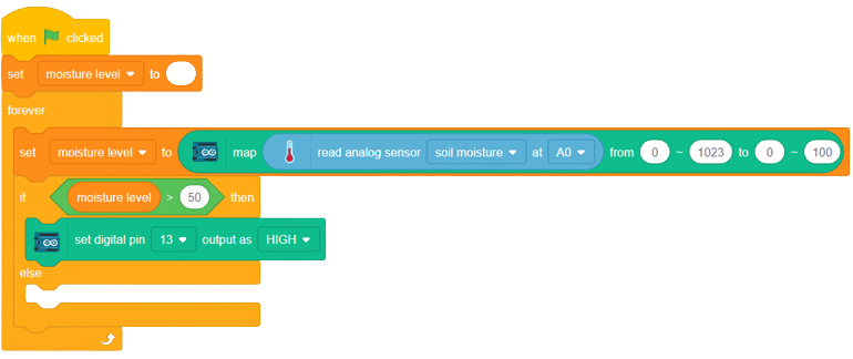
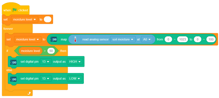
With these steps, your script is complete, and you can now monitor the soil moisture effectively using the soil moisture sensor and Arduino board. Happy gardening and farming!

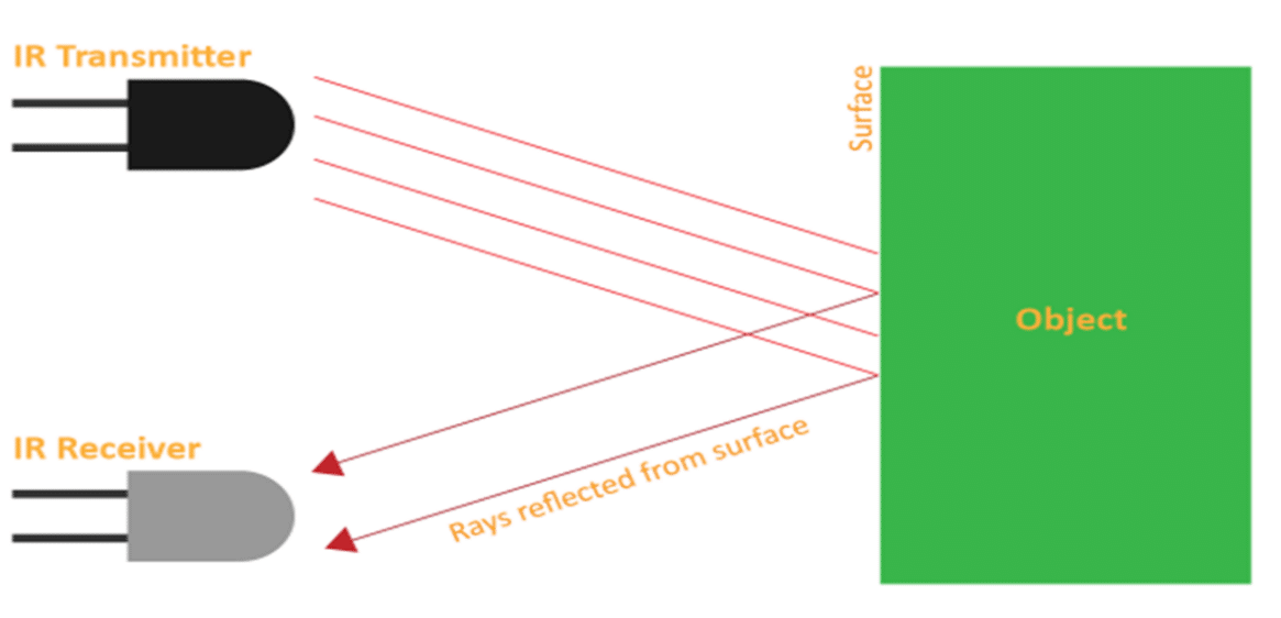
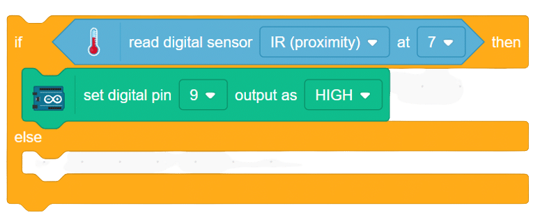
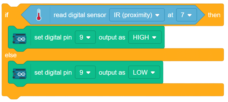
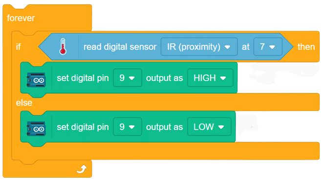
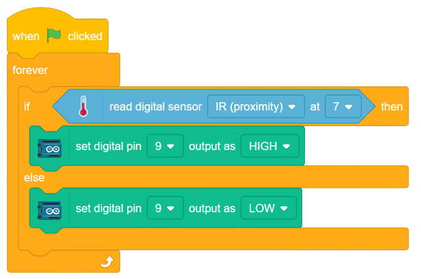
he IR (Infrared) sensor, a remarkable obstacle detection sensor, relies on the fundamental principle of light reflection. Within its compact module, the IR LED emits infrared radiation forward into its environment. As these radiant waves encounter any object along their path, they bounce back toward the sensor module. The photodiode, often identified by its black color, plays a crucial role in detecting these reflected rays.
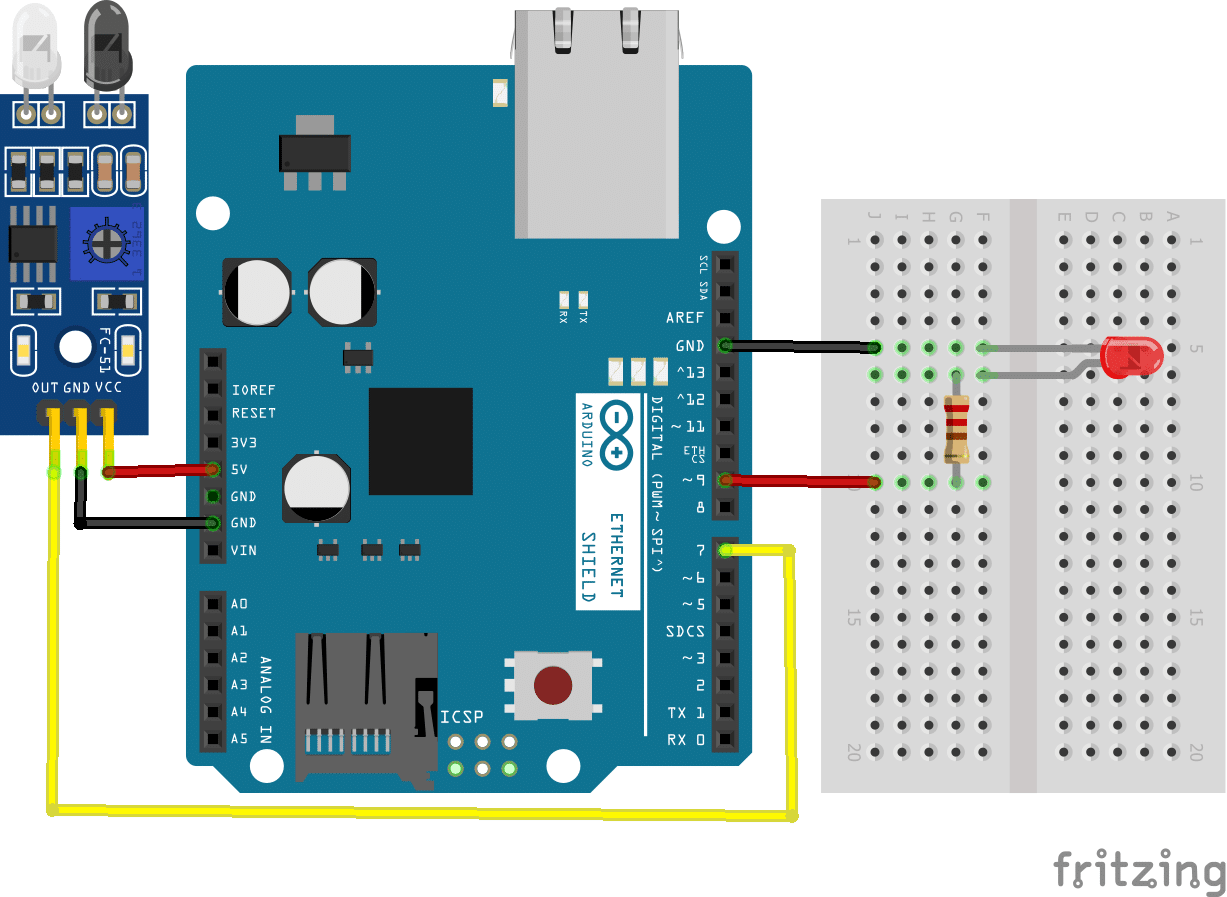
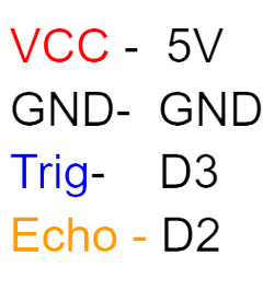
connection
IR_VCC – 5v
IR_GND – GND
IR_OUTPUT – D7
LED+ to D9
LED- to GND
Resistance -270
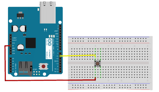
create a circuit on the breadboard as per the above circuit diagram
Steps :
Script
In this example, we are going to understand how to make a feed on Adafruit IO. Later we will write the Python code that will retrieve the information from the cloud and make the Quarky lights ON and OFF.
You can find the information about your account once you log in from here:
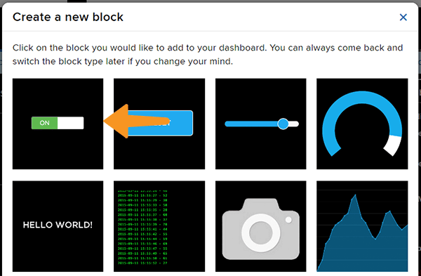
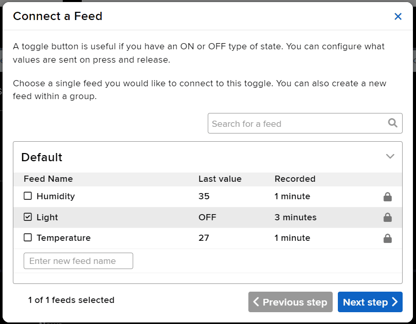
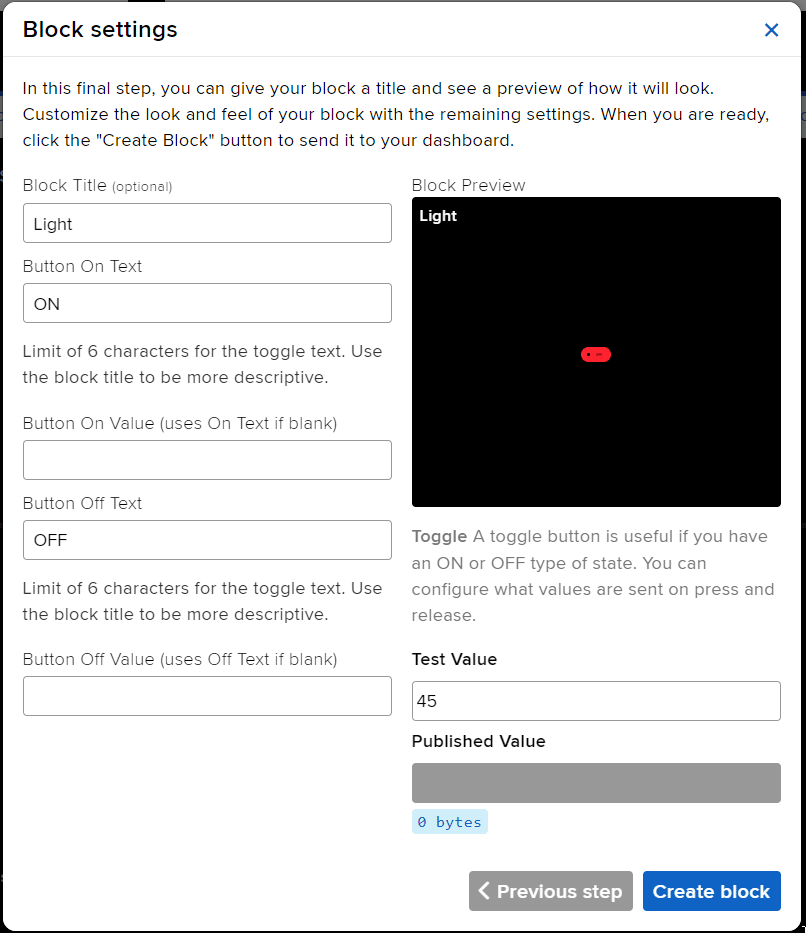
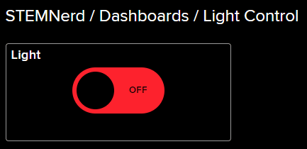
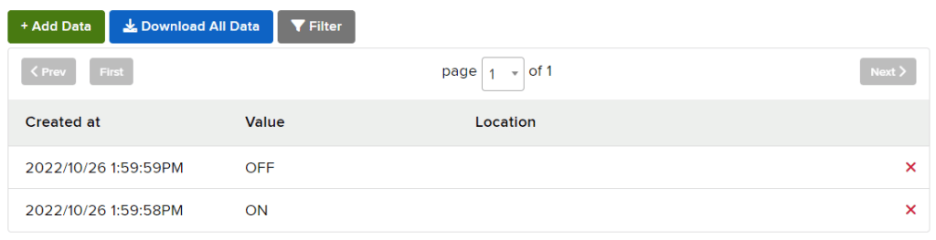
The following script reads the Light feed value and makes the Quarky light up accordingly.
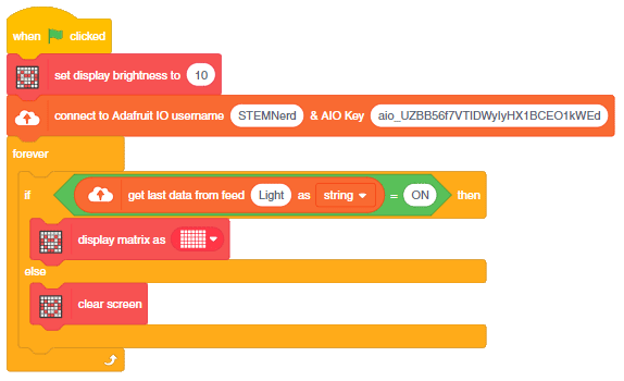
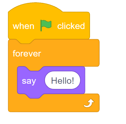
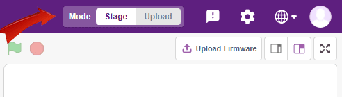
You can also make the script work independently of PictoBlox using the Upload Mode. For that switch to upload mode and replace the when green flag clicked block with when Quarky starts up block. Add the Wi-Fi connect blocks to connect Quarky to the Internet.
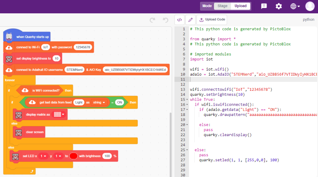
Download Code: https://pictoblox.page.link/HyUTYaW8VXX2XExK9
Troubleshooting:

In this example, we will make the computer program that controls a “quadruped” (a four-legged robot). It’s like a remote control car, except with four legs instead of four wheels. You can press different keys on the keyboard to make the quadruped move forward, backward, turn left and turn right.
The Quadruped will move according to the following logic:
The program uses the up, down, left, and right arrows to control the robot and make it move forward, backward, left, and right. Every time you press one of the arrows, Quarky will move in the direction you choose for 1000 steps.
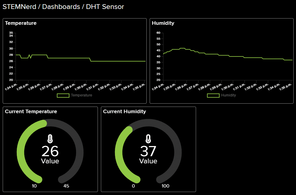
We will use the Adafruit IO cloud service to send data from a humidity and temperature sensor to the cloud in the Python Coding Environment of PictoBlox. Adafruit IO is a cloud service that allows you to send data from sensors and other devices to the cloud, where it can be stored and analyzed.
You can find the information about your account once you log in from here:
DHT sensors have 3 pins: GND, VCC, and Signal. You have to connect the following 3 pins to the Quarky Expansion Board:
# This code is used to connect to the internet and measure the temperature and humidity of the house.
# First, the Quarky object are created.
quarky = Quarky()
# Time module is imported.
import time
# AdaIO object is created.
adaio = AdaIO()
# IoTHouse object is created.
house = IoTHouse()
# Then, the connection to Adafruit IO is made.
adaio.connecttoadafruitio("STEMNerd", "aio_UZBB56f7VTIDWyIyHX1BCEO1kWEd")
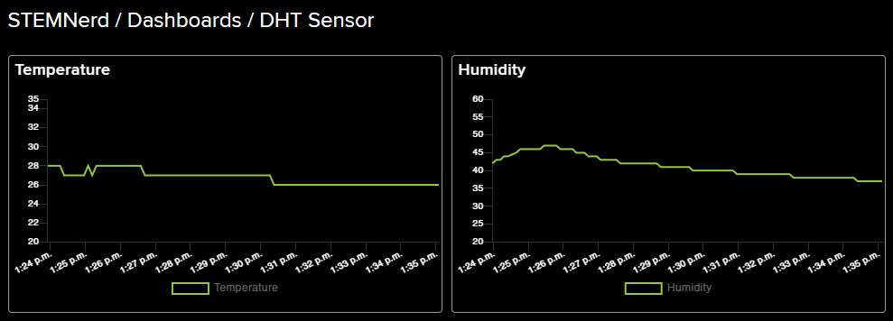
# The feeds for temperature and humidity are created.
adaio.createfeed("Temperature")
adaio.createfeed("Humidity")
# A while loop is used to measure the temperature and humidity continously.
while True:
# Temperature is measured using the dhtmeasure function.
adaio.createdata("Temperature", house.dhtmeasure(1, "D3"))
# The loop pauses for 1 second.
time.sleep(1)
# Humidity is measured using the dhtmeasure function.
adaio.createdata("Humidity", house.dhtmeasure(2, "D3"))
# The loop pauses for 5 seconds.
time.sleep(5)
The following feeds are created:
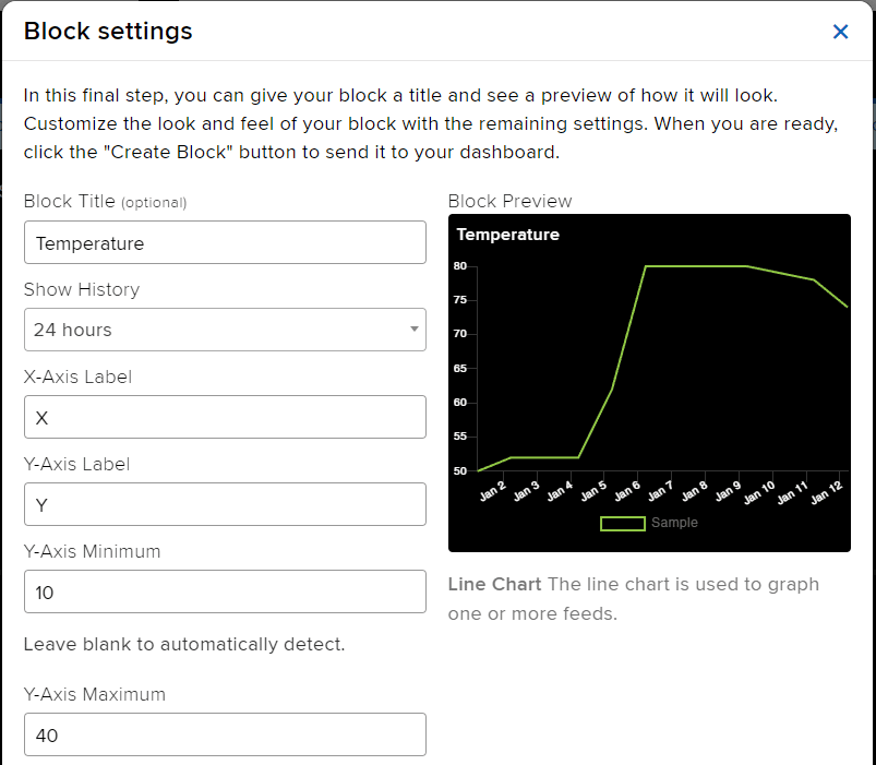
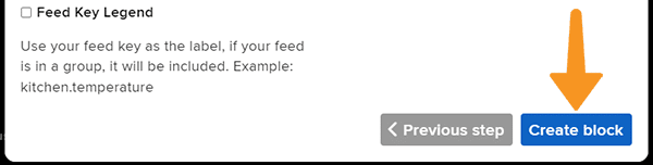
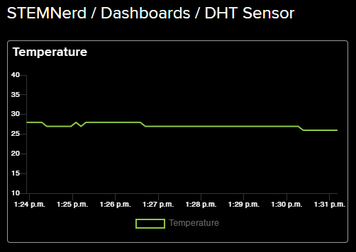
Follow the steps:
In this activity, we will make the computer program that controls the Mars Rover. It’s like a remote-control car. You can press different keys on the keyboard to make the Mars Rover move forward, backward, turn left and turn right.
In our Mars rover, there are a total of 6 motors and 5 servo motors.
The motors provide rotation to the wheels which helps the rover to attain motion in both forward and backward directions. All the left side motors (3 motors) are connected to the left motor port of Quarky and all the right side motors (3 motors) are connected to the right motor port of Quarky using a 3 port wire. This means that to control the Mars rover we have to control only 2 motors – Left and Right.
Also, there are 2 parameters to control – Direction (Forward or Backward) and Speed. With this control, the Mars rover can do all the desired motions.
The servo motors help in providing rotation to the complete wheel assembly so that the rover can change its wheel alignments and its path. These play a major role in turning cases of the Mars Rover.
We will need to turn the servo motors to the Inside Servo Position to make Mars Rover turn left and right.
Follow the steps:
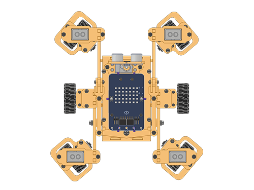 To control this position, you have set () to () block in the Mars Rover extension. Using this block, we can achieve this orientation.
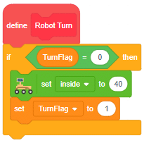
Forward-Backward Motions
Normal Right-Left Motions
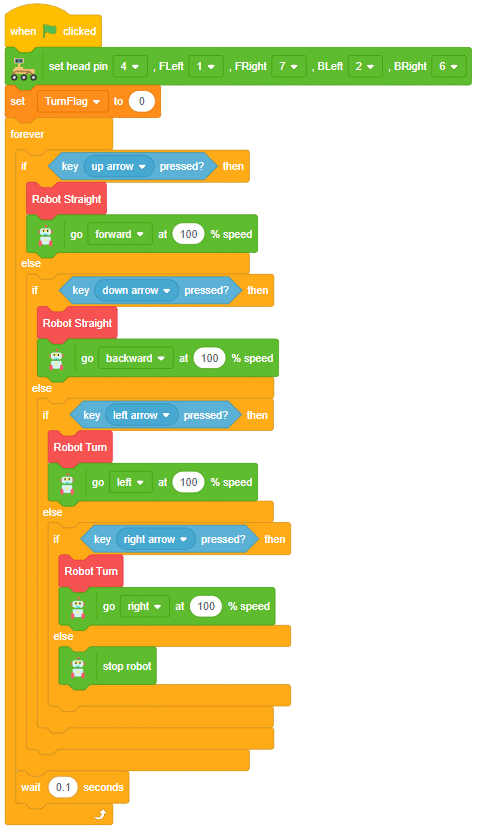
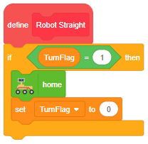
Our mission is accomplished! With the coding steps above, we were able to successfully control the Mars Rover using the Quarky extension when connected to PictoBlox. We set the motors and servo motors of the Mars Rover and used the set () to () and go () at () % speed blocks. Additionally, we created custom blocks for robot straight and robot turn orientation to get the desired forward and backward movements and right and left turns. This control will help the Mars Rover to achieve its desired tasks!
Instead of rotating the Mars Rover at a place to turn left or right, you can alternatives make the Mars Rover move in a circle.
The following code uses the four arrow keys to travel forward (up arrow key), backwards (down arrow key) , forward right in a circle( right arrow key) and forward left in a circle. (left arrow key)
We will also use the keys specially for backward left and right motion. We will use the “a” key for backward left motion and “d” key for backward right motion.
Make the code and play with the Mars Rover. Try to use different keys and combine different motions.
sprite=Sprite('Tobi')
import time
quarky = Quarky()
rover = MarsRover(4, 1, 7, 2, 6)
# setwheelsangle(Front Left = 40, Front Right = 40, Back Left = 90, Back Right = 90)
while True:
  if sprite.iskeypressed("up arrow"):
	  rover.home()
	  rover.setinangle(0)
	  quarky.runtimedrobot("F",100,2)

  if sprite.iskeypressed("down arrow"):
    rover.home()
    rover.setinangle(0)
    quarky.runtimedrobot("B",100,2)

  if sprite.iskeypressed("right arrow"):
    rover.home()
    rover.setrightturnangle(40)
    # rover.setwheelsangle(180,180,180,180)
    # rover.setheadangle(0)
    quarky.runtimedrobot("F",100,2)

  if sprite.iskeypressed("left arrow"):
    rover.home()
    rover.setleftturnangle(40)
    # rover.setwheelsangle(0,0,0,0)
    quarky.runtimedrobot("F",100,2)

  if sprite.iskeypressed("A"):
    rover.home()
    rover.setleftturnangle(40)
    quarky.runtimedrobot("B",100,2)

  if sprite.iskeypressed("D"):
    rover.home()
    rover.setrightturnangle(40)
quarky.runtimedrobot("B",100,2)Circular Right-Left Motion:

A sign detector Mars Rover robot is a robot that can recognize and interpret certain signs or signals, such as hand gestures or verbal commands, given by a human. The robot uses sensors, cameras, and machine learning algorithms to detect and understand the sign, and then performs a corresponding action based on the signal detected.
These robots are often used in manufacturing, healthcare, and customer service industries to assist with tasks that require human-like interaction and decision making.
sprite = Sprite('Tobi')
# sprite = Sprite('Tobi')
quarky = Quarky()
import time

recocards = RecognitionCards()
rover = MarsRover(4, 1, 7, 2, 6)

recocards.video("on flipped")
recocards.enablebox()
recocards.setthreshold(0.6)

while True:
  recocards.analysecamera()
  sign = recocards.classname()
  sprite.say(sign + ' detected')

  if recocards.count() > 1:
    if 'Go' in sign:
      rover.home()
      rover.setinangle(0)
      quarky.runtimedrobot("F",100,3)

    if 'Turn Left' in sign:
      rover.home()
      rover.setinangle(40)
      quarky.runtimedrobot("L",100,3)

    if 'Turn Right' in sign:
      rover.home()
      rover.setinangle(40)
      quarky.runtimedrobot("R",100,3)

    if 'U Turn' in sign:
      rover.home()
      rover.setinangle(0)
quarky.runtimedrobot("B",100,3)Forward-Backward Motions:

Right-Left Motions:
A sign detector Mars Rover robot is a robot that can recognize and interpret certain signs or signals, such as hand gestures or verbal commands, given by a human. The robot uses sensors, cameras, and machine learning algorithms to detect and understand the sign, and then performs a corresponding action based on the signal detected.
These robots are often used in manufacturing, healthcare, and customer service industries to assist with tasks that require human-like interaction and decision making.
Initializing the Functions:
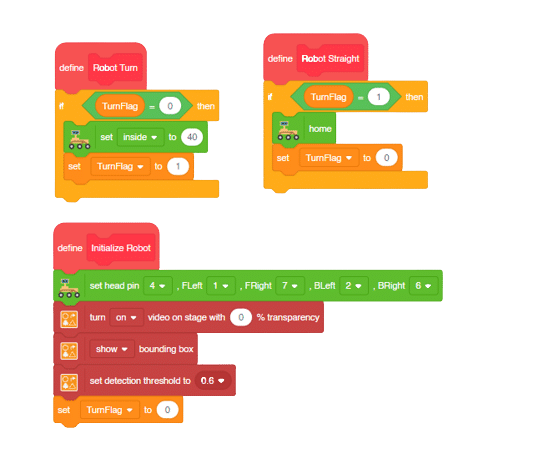
Main Code
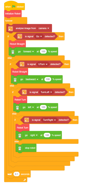
Forward-Backward Motions:
Right-Left Motions:


Copyright 2025 – Agilo Research Pvt. Ltd. All rights reserved – Terms & Condition | Privacy Policy