Image Classifier is an extension of the ML environment that allows users to classify images into different classes. This feature is available only in the desktop version of PictoBlox for Windows, macOS, or Linux. As part of the Image Classifier workflow, users can add classes, upload data, train the model, test the model, and export the model to the Block Coding Environment.
Let’s create the ML model.
Opening Image Classifier Workflow
Alert: The Machine Learning Environment for model creation is available in the only desktop version of PictoBlox for Windows, macOS, or Linux. It is not available in Web, Android, and iOS versions.
Follow the steps below:
- Open PictoBlox and create a new file.
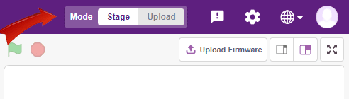
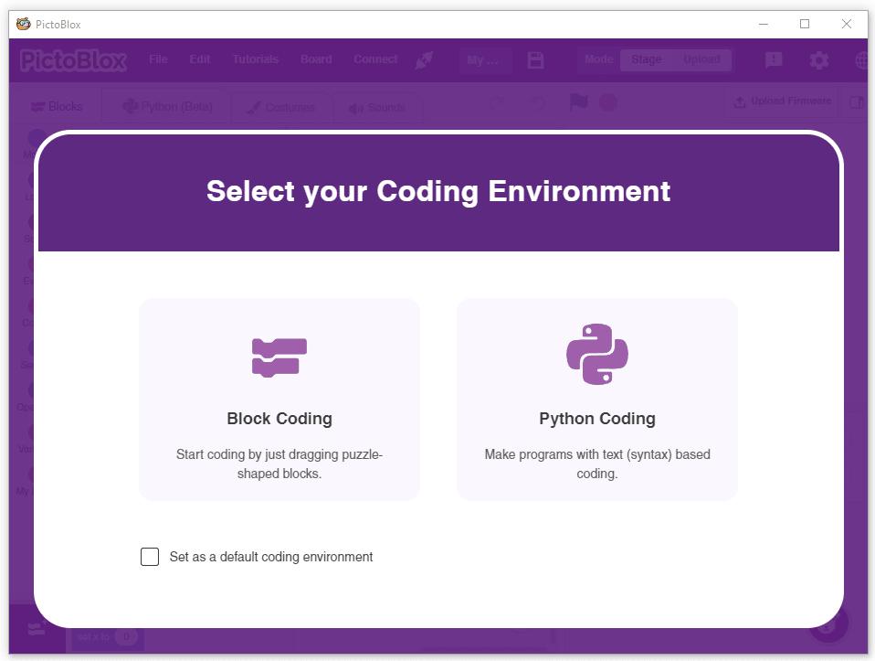
- Select the coding environment as Block Coding Environment.
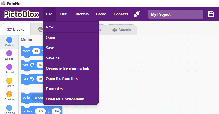
- Select the “Open ML Environment” option under the “Files” tab to access the ML Environment.
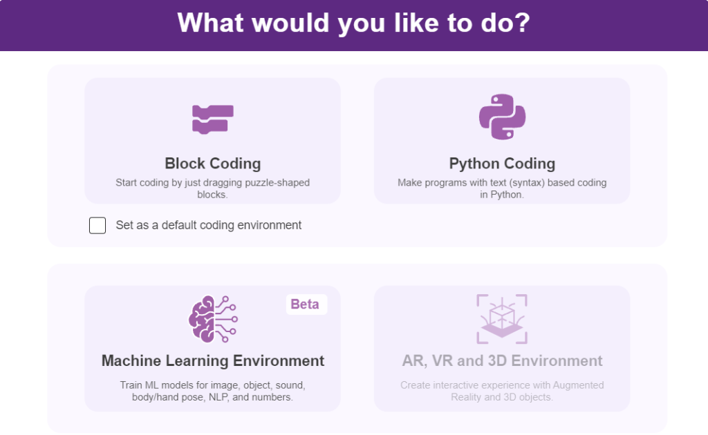
- You’ll be greeted with the following screen.
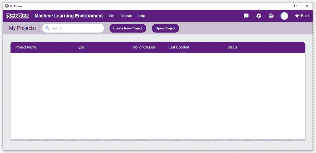 Click on “Create New Project“.
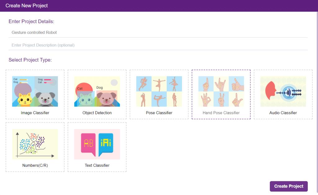
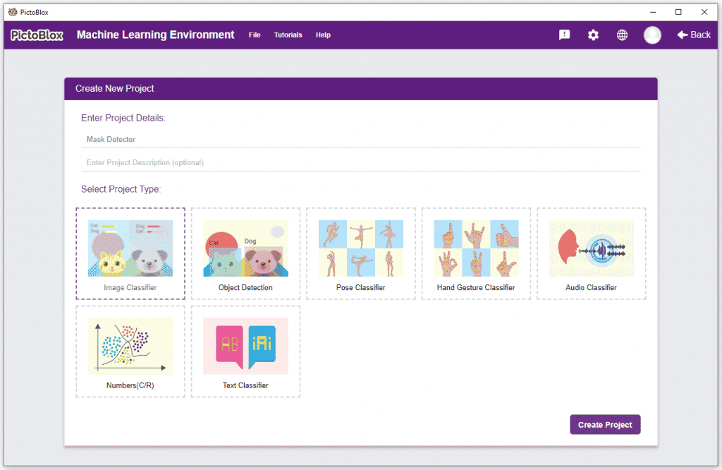
- A window will open. Type in a project name of your choice and select the “Image Classifier” extension. Click the “Create Project” button to open the Image Classifier window.
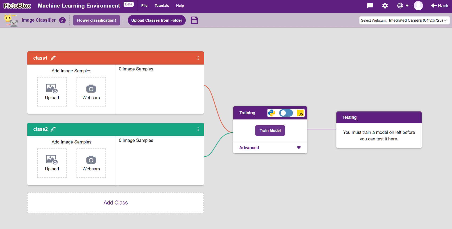
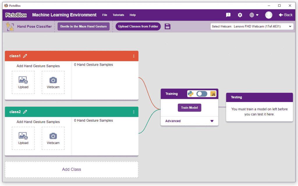
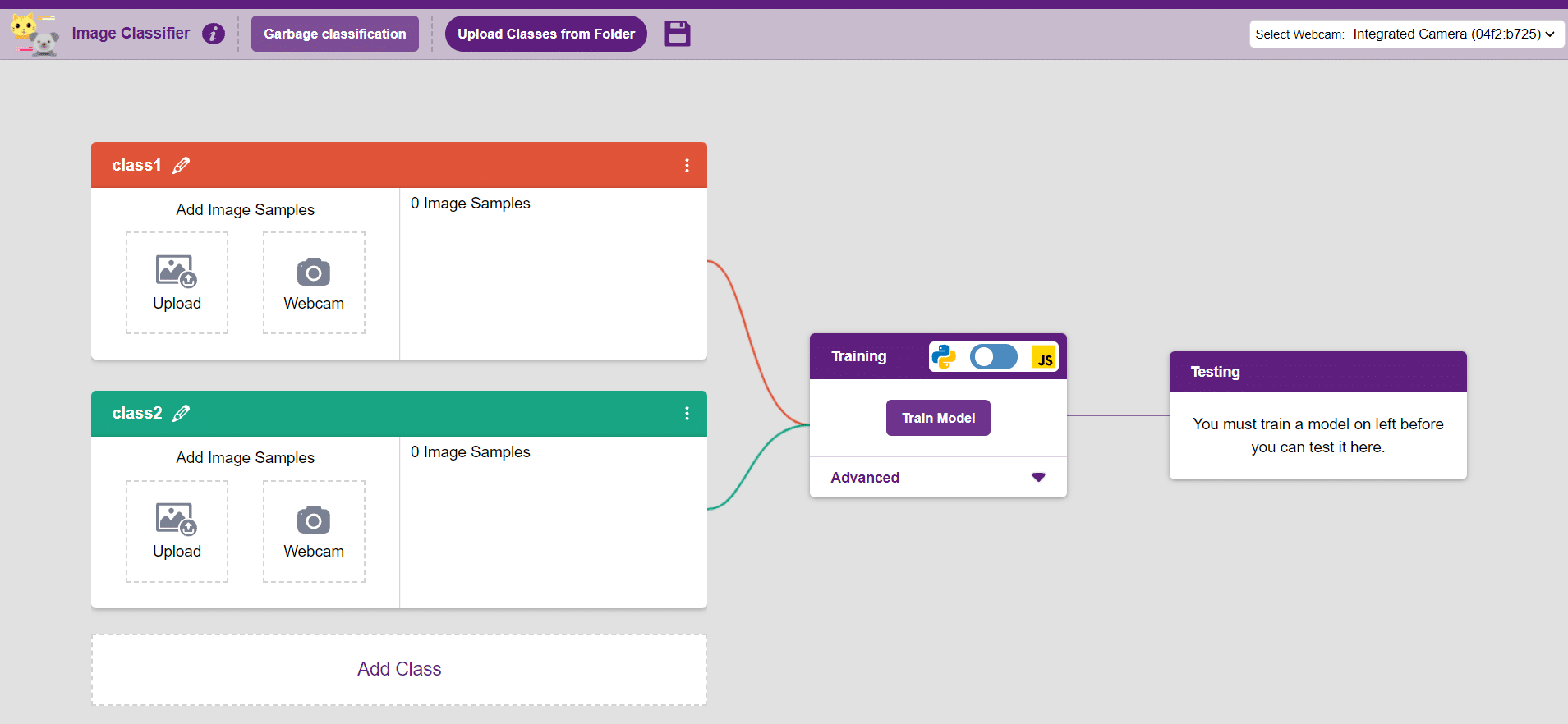
- You shall see the Image Classifier workflow with two classes already made for you. Your environment is all set. Now it’s time to upload the data.
Class in Image Classifier
Class is the category in which the Machine Learning model classifies the images. Similar images are put in one class.
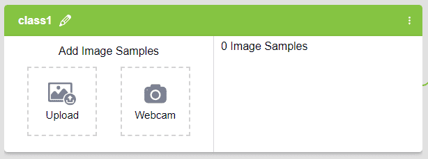
There are 2 things that you have to provide in a class:
- Class Name: It’s the name to which the class will be referred as.
- Image Data: This data can either be taken from the webcam or by uploading from local storage.
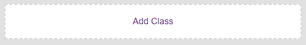
Note: You can add more classes to the projects using the Add Class button.
Adding Data to Class
You can perform the following operations to manipulate the data into a class.
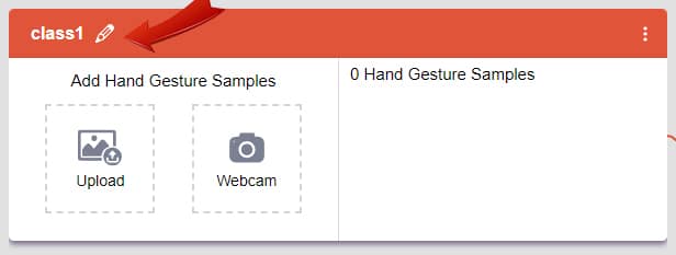
- Naming the Class: You can rename the class by clicking on the edit button.
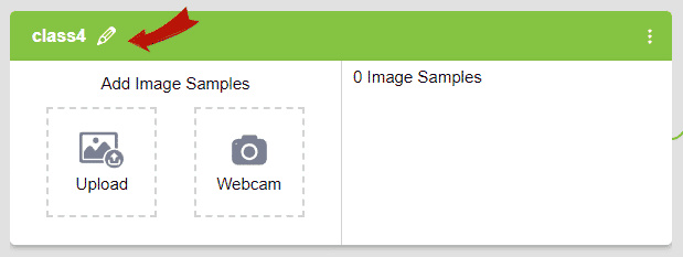
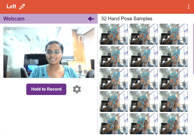
- Adding Data to the Class: You can add the data using by Uploading the files from the local folder or the Webcam.
Training the Model
After data is added, it’s fit to be used in model training. In order to do this, we have to train the model. By training the model, we extract meaningful information from the images, which in turn updates the weights. Once these weights are saved, we can use our model to make predictions on data previously unseen.
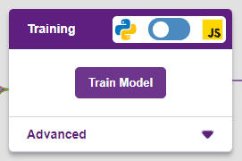
However, before training the model, there are a few hyperparameters that you should be aware of. Click on the “Advanced” tab to view them.
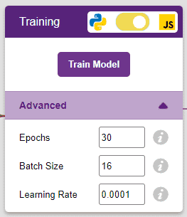
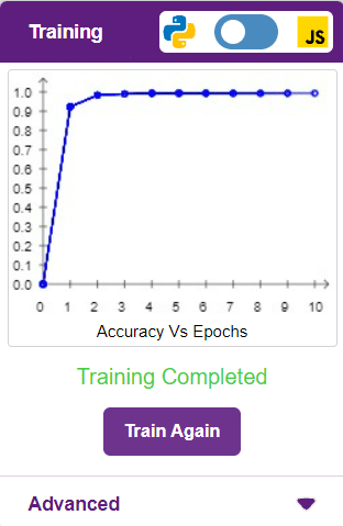
It’s a good idea to train an image classification model for a high number of epochs. The model can be trained in both JavaScript and Python. In order to choose between the two, click on the switch on top of the Training panel.
Note: These hyperparameters can affect the accuracy of your model to a great extent. Experiment with them to find what works best for your data.
Alert: Dependencies must be downloaded to train the model in Python, JavaScript will be chosen by default.
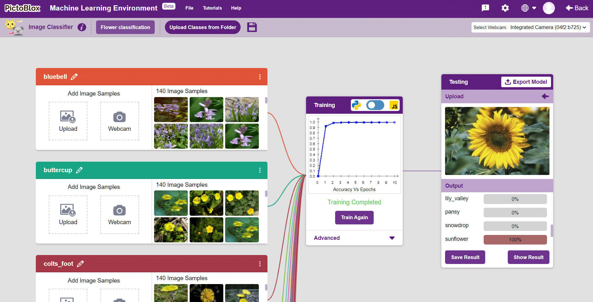
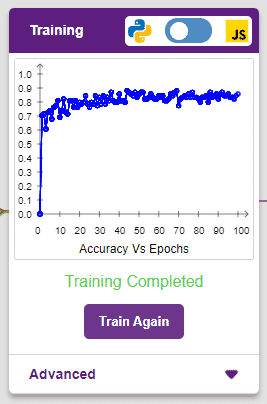
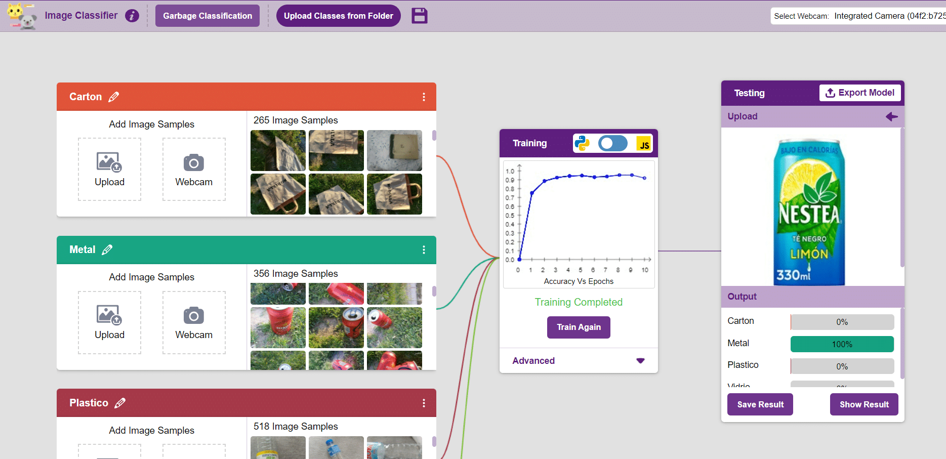
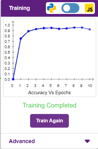
The accuracy of the model should increase over time. The x-axis of the graph shows the epochs, and the y-axis represents the accuracy at the corresponding epoch. Remember, the higher the reading in the accuracy graph, the better the model. The x-axis of the graph shows the epochs, and the y-axis represents the corresponding accuracy. The range of accuracy is 0 to 1.
Other evaluating parameters can see by clicking on Train Report
Here we can see the confusion matrix and training accuracy of individual classes after training.
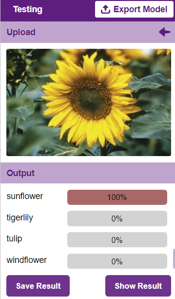
Testing the Model
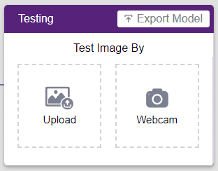
To test the model, simply enter the input values in the “Testing” panel and click on the “Predict” button.
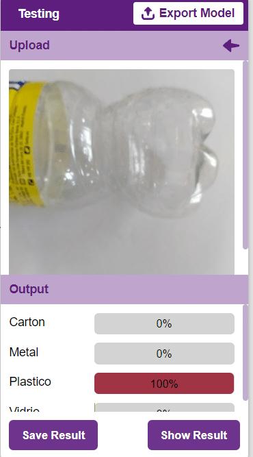
The model will return the probability of the input belonging to the classes.
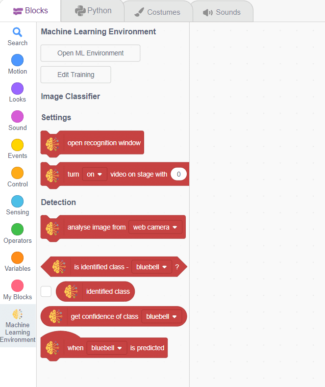
Export in Block Coding
Click on the “Export Model” button on the top right of the Testing box, and PictoBlox will load your model into the Block Coding Environment if you have opened the ML Environment in the Block Coding.
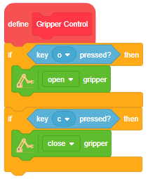
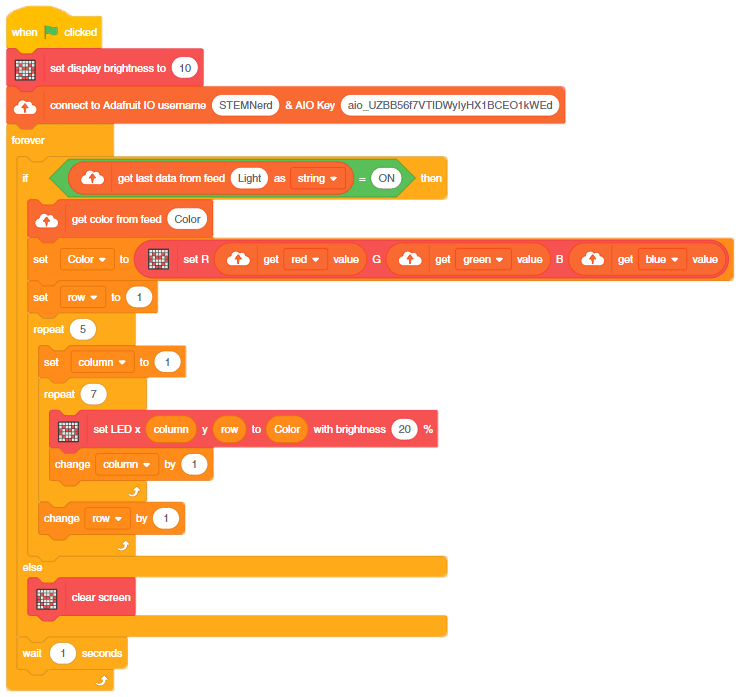
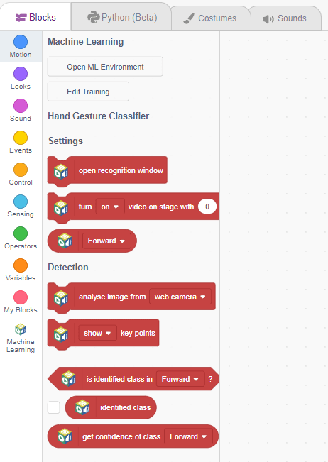
Code
The idea is simple, we’ll add image samples in the “Backdrops” column. We’ll keep cycling through the backdrops and keep classifying the image on the stage.
- Add testing images in the backdrop and delete the default backdrop.

- Now, come back to the coding tab and select the Tobi sprite.
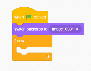
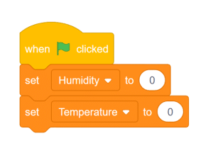
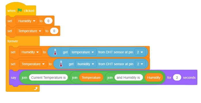
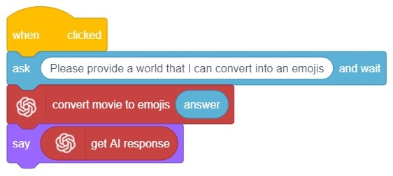
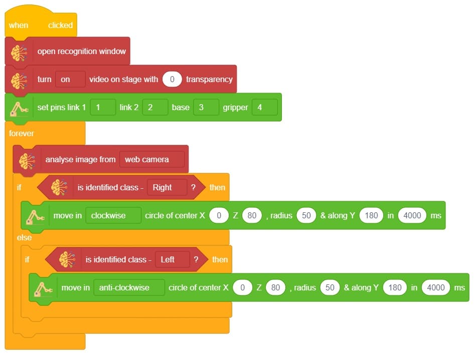
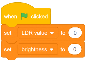
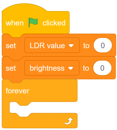
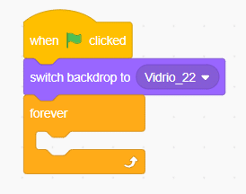
- We’ll start by adding a when flag clicked block from the Events palette.
- Add switch backdrop to () block from the Looks palette. Select any image.
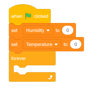
- Add a forever block from the Control palette.
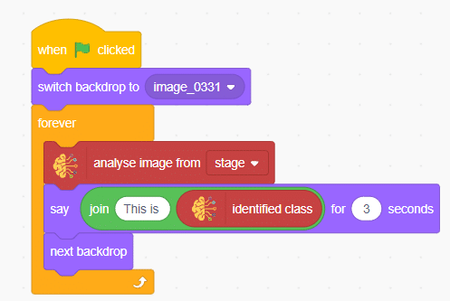
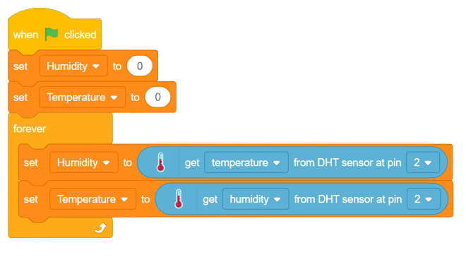
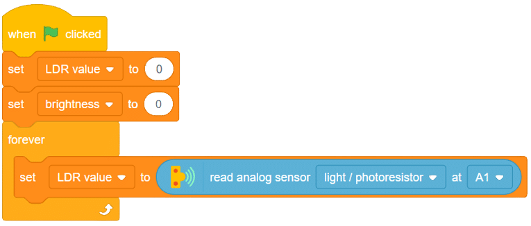
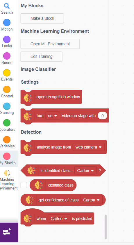
- Inside the forever block add an analyze image from () block from the Machine Learning palette.
- Add two blocks of say () for () seconds from the Looks palette.
- Inside the say block add join () () block from operator palette.
- Inside the join block write statement at first empty place and at second empty place add identified class from the Machine Learning palette.
- Finally, add the next backdrop block from the Looks palette below the () bounding box block.
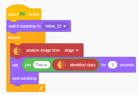
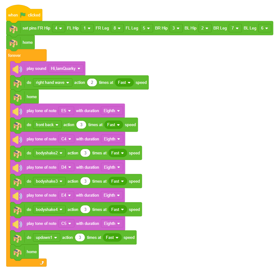
Final Result
You can build more applications on top of this waste classifier.