In this activity, we will create a custom activity where you will be able to move the Mecanum robot in a square effortlessly along with making an Axe type figure.
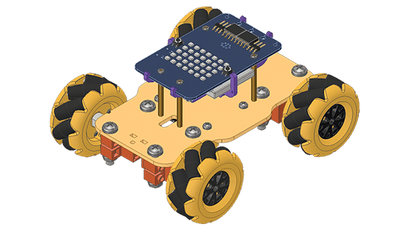
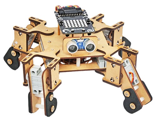
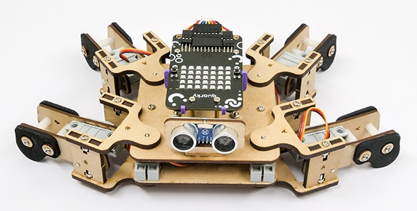
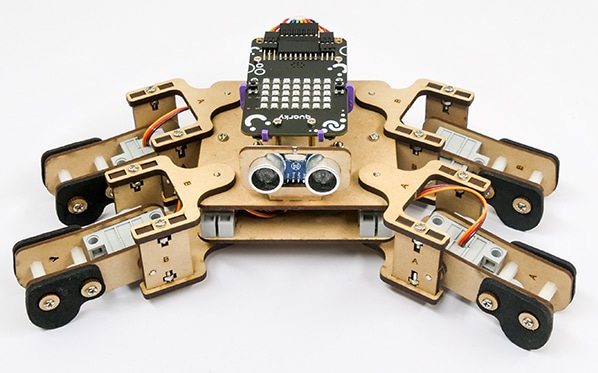
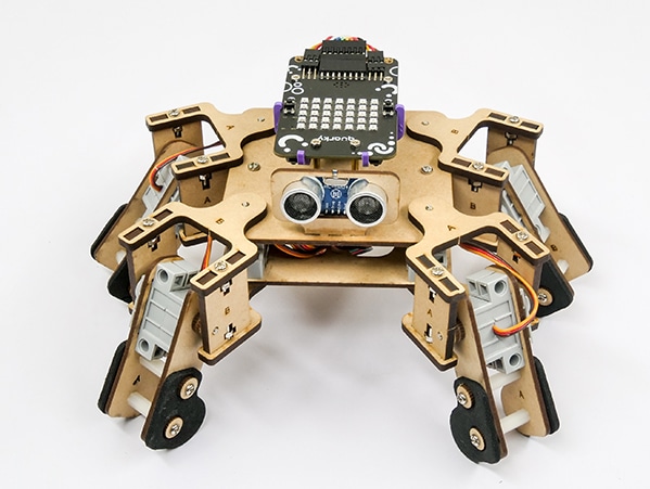
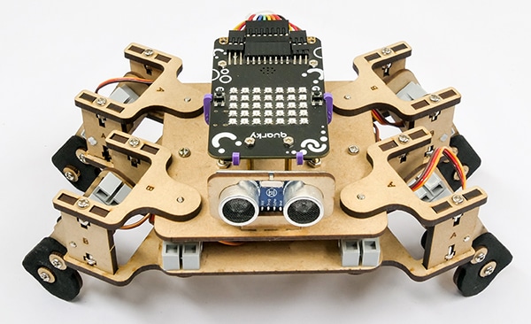
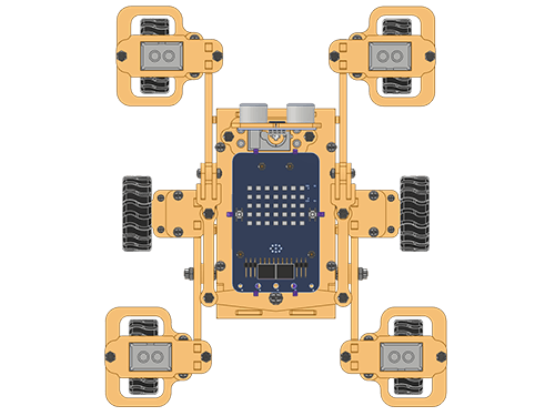
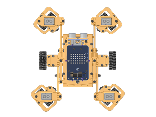
The Quarky Mecanum Wheel Robot is a type of robot that uses a special type of wheel to move. The wheel is made of four rollers mounted at 45- degree angles to the wheel’s hub. Each roller has its own motor and can spin in either direction. This allows the wheel to move in any direction, making it an ideal choice for navigating around obstacles.
Coding Steps
Follow the steps:
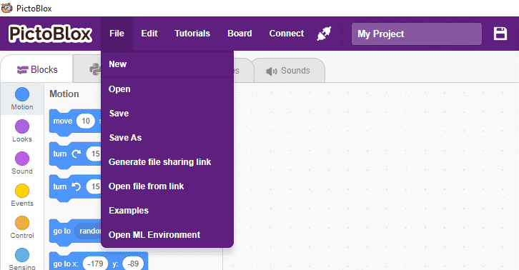
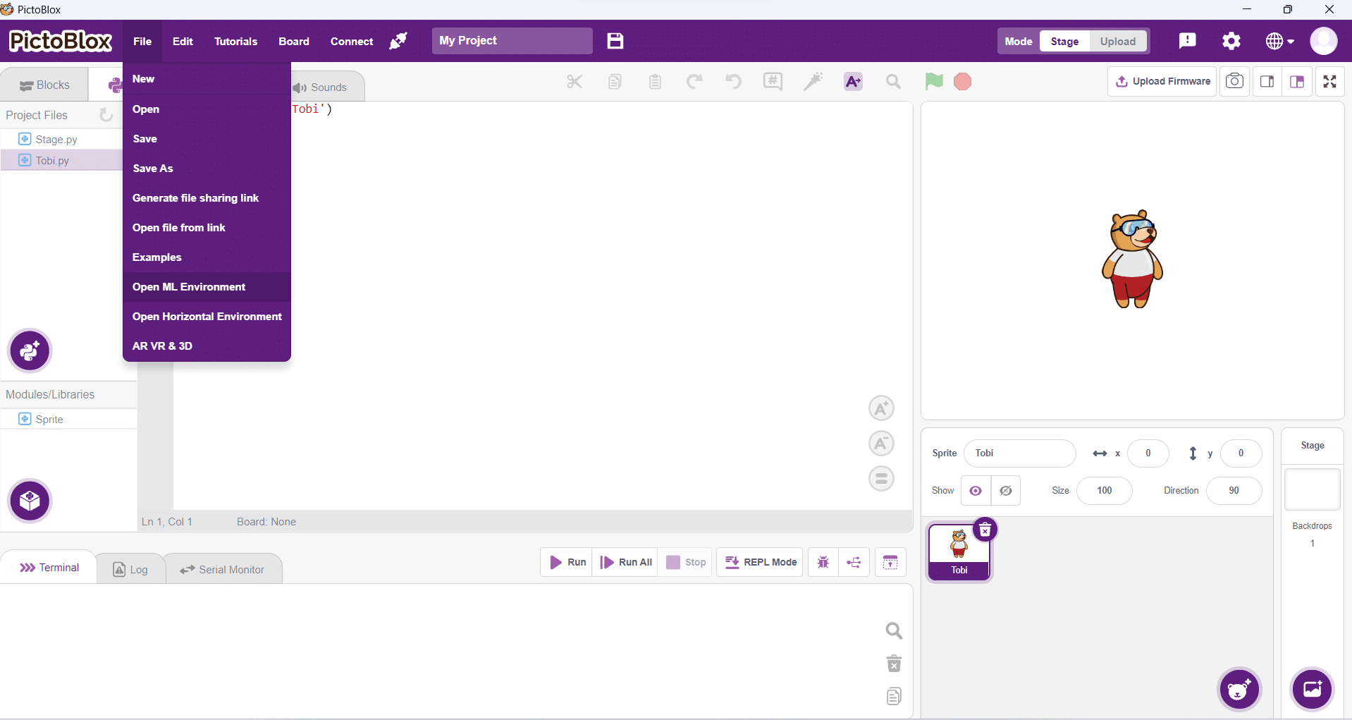
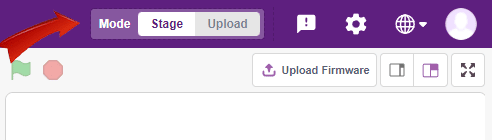
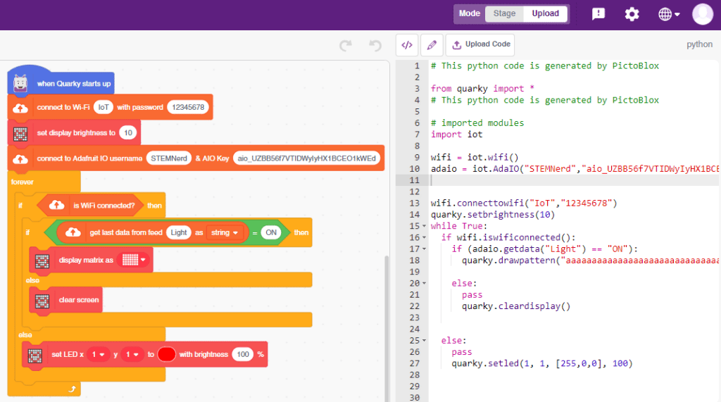
- Open a new project in PictoBlox and select Python Coding Environment.
- Connect Quarky to PictoBlox.
- Click on the Add Extension button and add the Quarky Mecanum extension.
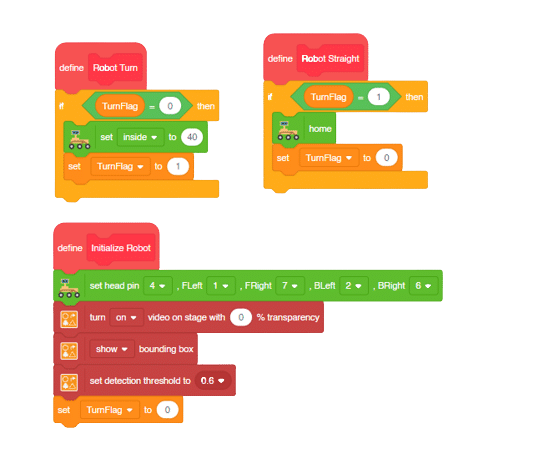
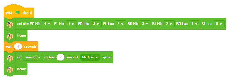
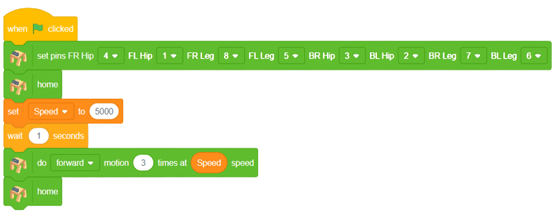
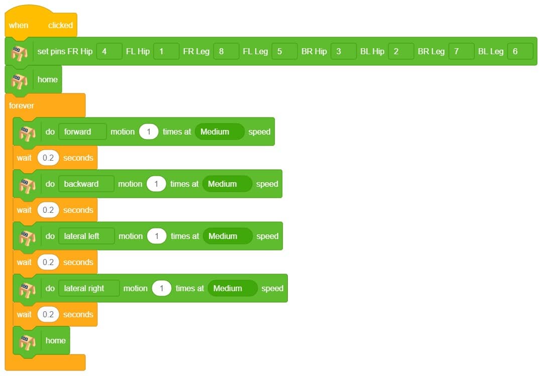
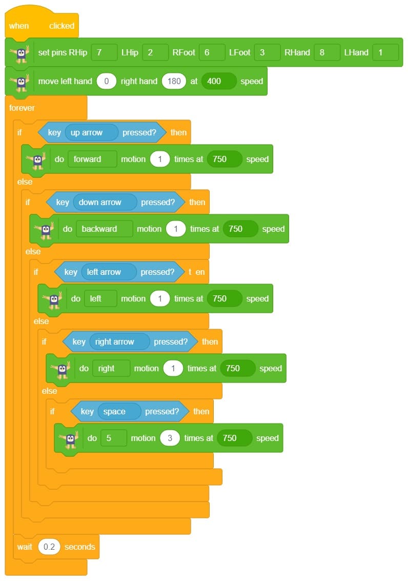
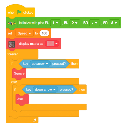
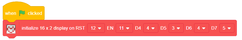
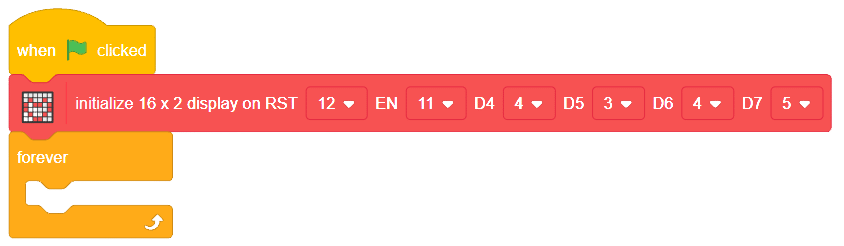
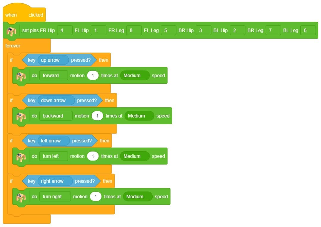
- Now we will first initialize the Mecanum robots and the servos before starting the main code.
- Here there are two parts specifically : To make a Square and To make an Axe
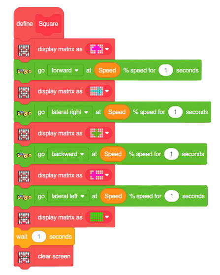
To make a Square (Logic):
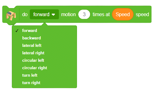
The main steps would include to display the lights in arrow forms before implementing the specific move. The moves would be implemented in the following order:
Forward -> Lateral Right -> Backward -> Lateral Left.
Code for Square Motion:
def Square():
quarky.drawpattern("jjjgjjjjjgggjjjgggggjjjjgjjjjjjgjjj")
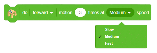
meca.runtimedrobot("forward",Speed,1)
quarky.drawpattern("jjjjfjjjjjjffjfffffffjjjjffjjjjjfjj")
meca.runtimedrobot("lateral right",Speed,1)
quarky.drawpattern("jjjcjjjjjjcjjjjcccccjjjcccjjjjjcjjj")
meca.runtimedrobot("backward",Speed,1)
quarky.drawpattern("jjgjjjjjggjjjjgggggggjggjjjjjjgjjjj")
meca.runtimedrobot("lateral left",Speed,1)
quarky.drawpattern("ccccccccccccccccccccccccccccccccccc")
time.sleep(1)
quarky.cleardisplay()
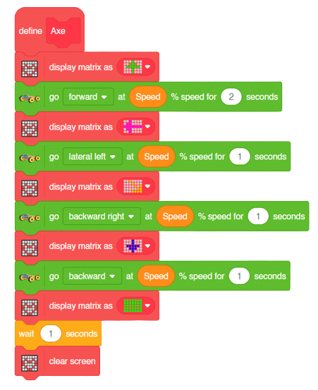
To make an Axe (Logic):
The main steps would include to display the lights in arrow forms before implementing the specific move. The moves would be implemented in the following order:
Forward ( 2 steps ) -> Lateral Left ( 1 step ) -> Backward Right ( 1 step ) -> Backward ( 1 step )
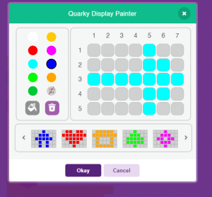
We will display the arrows with the help of Quarky LED’s and implement the code.
Code for Axe Motion:
def Axe():
    quarky.drawpattern("jjjcjjjjjcccjjjcccccjjjjcjjjjjjcjjj")
    meca.runtimedrobot("forward",Speed,2)
    quarky.drawpattern("jjgjjjjjggjjjjgggggggjggjjjjjjgjjjj")
    meca.runtimedrobot("lateral left",Speed,1)
    quarky.drawpattern("jjhjjjjjjjhjjjjjjjhjhjjjjjhhjjjhhhh")
    meca.runtimedrobot("backward right",Speed,1)
    quarky.drawpattern("jjjdjjjjjjdjjjjdddddjjjdddjjjjjdjjj")
    meca.runtimedrobot("backward",Speed,1)
    quarky.drawpattern("ccccccccccccccccccccccccccccccccccc")
    time.sleep(1)
    quarky.cleardisplay()
Main Code
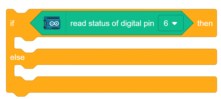
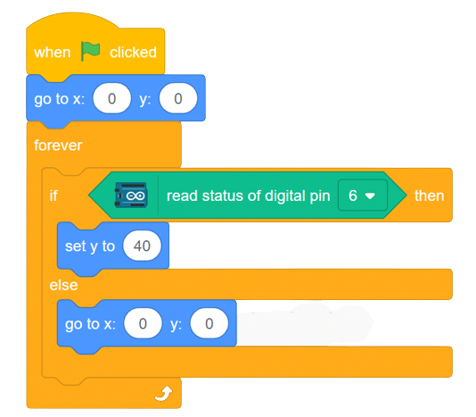
Now we will keep a specific condition on when to activate the Square Motion and when to activate the Axe Motion.
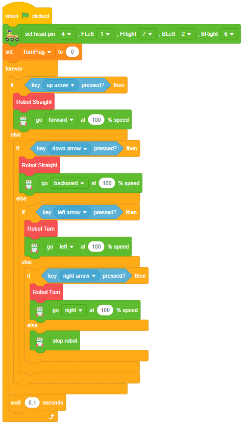
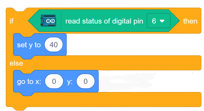
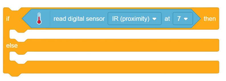
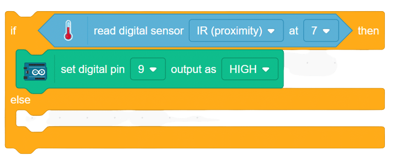
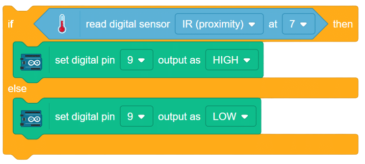
We will use the if-else conditions where on pressing the “up” arrow key, we will initiate the Square Motion and on pressing the “down” arrow key, we will initiate the Axe Motion with the help of Mecanum Robot.
sprite = Sprite('Tobi')
quarky=Quarky()
import time

def Square():
    quarky.drawpattern("jjjgjjjjjgggjjjgggggjjjjgjjjjjjgjjj")
    meca.runtimedrobot("forward",Speed,1)
    quarky.drawpattern("jjjjfjjjjjjffjfffffffjjjjffjjjjjfjj")
    meca.runtimedrobot("lateral right",Speed,1)
    quarky.drawpattern("jjjcjjjjjjcjjjjcccccjjjcccjjjjjcjjj")
    meca.runtimedrobot("backward",Speed,1)
    quarky.drawpattern("jjgjjjjjggjjjjgggggggjggjjjjjjgjjjj")
    meca.runtimedrobot("lateral left",Speed,1)
    quarky.drawpattern("ccccccccccccccccccccccccccccccccccc")
    time.sleep(1)
    quarky.cleardisplay()

def Axe():
    quarky.drawpattern("jjjcjjjjjcccjjjcccccjjjjcjjjjjjcjjj")
    meca.runtimedrobot("forward",Speed,2)
    quarky.drawpattern("jjgjjjjjggjjjjgggggggjggjjjjjjgjjjj")
    meca.runtimedrobot("lateral left",Speed,1)
    quarky.drawpattern("jjhjjjjjjjhjjjjjjjhjhjjjjjhhjjjhhhh")
    meca.runtimedrobot("backward right",Speed,1)
    quarky.drawpattern("jjjdjjjjjjdjjjjdddddjjjdddjjjjjdjjj")
    meca.runtimedrobot("backward",Speed,1)
    quarky.drawpattern("ccccccccccccccccccccccccccccccccccc")
    time.sleep(1)
    quarky.cleardisplay()


meca=Mecanum(1,2,7,8)


Speed = 100
quarky.drawpattern("jjjjjjjjjjjjjjjjjjjjjjjjjjjjjjjjjjj")
while True:
  if sprite.iskeypressed("up arrow"):
    Square()
  else:
    if sprite.iskeypressed("down arrow"):
      Axe()
Final Output
Square Motion:

Axe Motion:


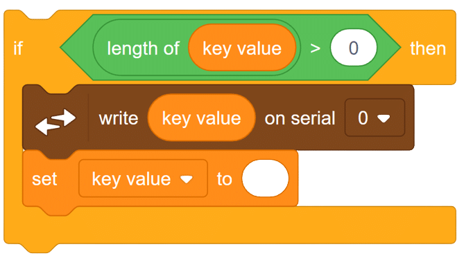


 To control this position, you have set () to () block in the Mars Rover extension. Using this block, we can achieve this orientation.